Service Data: 0C-13
Tightening Torque Chart
For other bolts and nuts not listed in the preceding page, refer to this chart:
Rear brake cam lever nut 11 1.1 8.0
Rear axle housing mounting bolt (Final gear case) 55 5.5 40.0
Rear axle housing mounting bolt (Swingarm) 60 6.0 43.5
Rear shock absorber mounting nut
Upper 35 3.5 25.5
Lower 60 6.0 43.5
Rear swingarm pivot nut 102 10.2 74.0
Brake disc cover mounting bolt 12 1.2 8.5
Brake pipe flare nut 16 1.6 11.5
Master cylinder holder bolt (Upper & Lower) 10 1.0 7.0
Brake lever pivot bolt 6 0.6 4.5
Brake lever pivot bolt lock-nut 6 0.6 4.5
Rear brake pedal pivot nut 12 1.2 8.5
Front brake pad mounting pin 18 1.8 13.0
Front brake hose union bolt 23 2.3 16.5
Caliper holder slide pin nut 23 2.3 16.5
Caliper holder pin 18 1.8 13.0
Rear brake anchor panel nut 32 3.2 23.0
Steering shaft lower nut 49 4.9 35.5
Front carrier mounting bolt 28 2.8 20.0
Rear carrier mounting bolt 28 2.8 20.0
Front grip bar mounting bolt 28 2.8 20.0
Item N⋅m kgf-m lb-ft
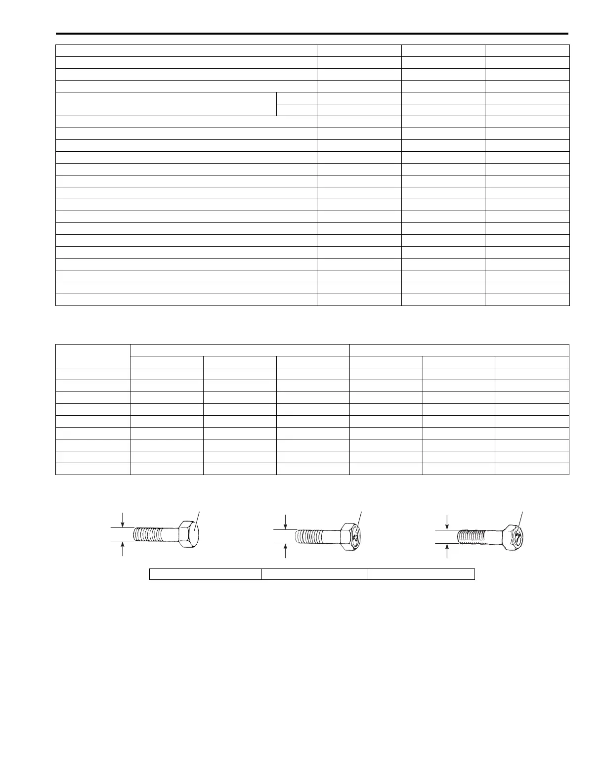
Bolt Diameter
“a” (mm)
Conventional or “4” marked bolt “7” marked bolt
N⋅mkgf-mlb-ft N⋅mkgf-mlb-ft
4 1.5 0.15 1.0 2.3 0.23 1.5
5 3 0.3 2.0 4.5 0.45 3.0
6 5.5 0.55 4.0 10 1.0 7.0
8 131.39.5232.316.5
10 29 2.9 21.0 50 5.0 36.0
12 45 4.5 32.5 85 8.5 61.5
14 65 6.5 47.0 135 13.5 97.5
16 105 10.5 76.0 210 21.0 152.0
18 160 16.0 115.5 240 24.0 173.5
321
“a”
“a”
“a”
I649G1030001-04
1. Conventional bolt 2. “4” marked bolt 3. “7” marked bolt
 Loading...


