ENGINE GENERAL INFORMATION AND DIAGNOSIS (TBI FOR G10) 6-49
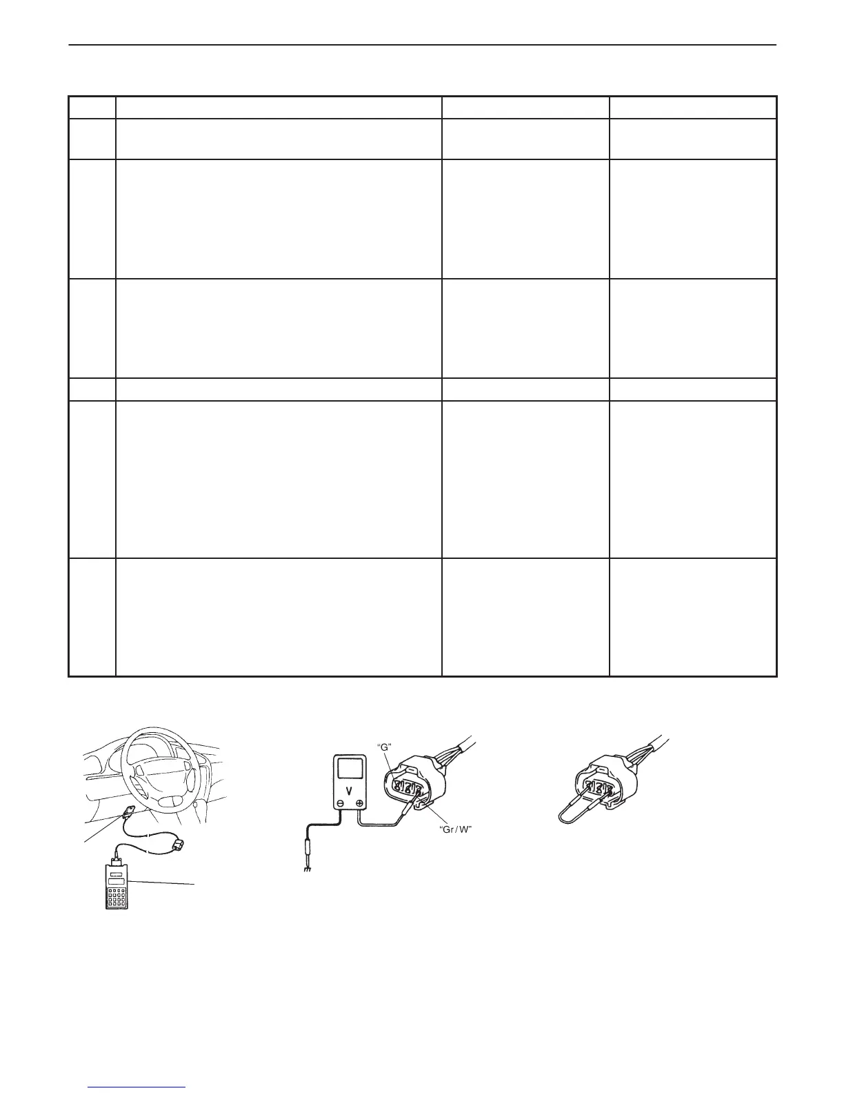
Fig. 1 for Step 2 Fig. 2 for Step 3 Fig. 3 for Step 4
Scan tool
DLC
INSPECTION
STEP ACTION YES NO
1 Was “ENGINE DIAG. FLOW TABLE” performed? Go to Step 2. Go to “ENGINE DIAG.
FLOW TABLE”.
2 Check ECT Sensor and Its Circuit.
1) Connect scan tool with ignition switch OFF.
2) Turn ignition switch ON.
3) Check engine coolant temp. displayed on scan
tool. See Fig. 1.
Is –40_C (–40_F) or 119_C (246_F) indicated?
Go to Step 3. Intermittent trouble.
Check for intermittent
referring to “Intermittent
and Poor Connection”
in Section 0 A.
3 Check Wire Harness.
1) Disconnect ECT sensor connector.
2) Check engine coolant temp. displayed on scan
tool.
Is –40_C (–40_F) indicated?
Replace ECT sensor. “Gr/W” wire shorted to
ground.
If wire is OK, substitute
a known-good ECM
(PCM) and recheck.
4 Does scan tool indicate –40_C (–40_F) at Step 2. Go to Step 6. Go to Step 5.
5 Check Wire Harness.
1) Disconnect ECT sensor connector with
ignition switch OFF.
2) Check for proper connection to ECT sensor at
“G” and “Gr/W” wire terminals.
3) If OK, then with ignition switch ON, is voltage
applied to “G” wire terminal about 4 – 6 V?
See Fig. 2.
Go to Step 4. “Gr/W” wire open or
shorted to power, or
poor C01-7 connection.
If wire and connection
are OK, substitute a
known-good ECM
(PCM) and recheck.
6 Check Wire Harness.
1) Using service wire, connect ECT sensor
connector terminals. See Fig. 3.
2) Turn ignition switch ON and check engine
coolant temp. displayed on scan tool.
Is 119_C (246_F) indicated?
Replace ECT sensor. “G” wire open or
poor C01-9 connection.
If wire and connection
are OK, substitute a
known-good ECM
(PCM) and recheck.