6-38 ENGINE GENERAL INFORMATION AND DIAGNOSIS (TBI FOR G10)
1
2
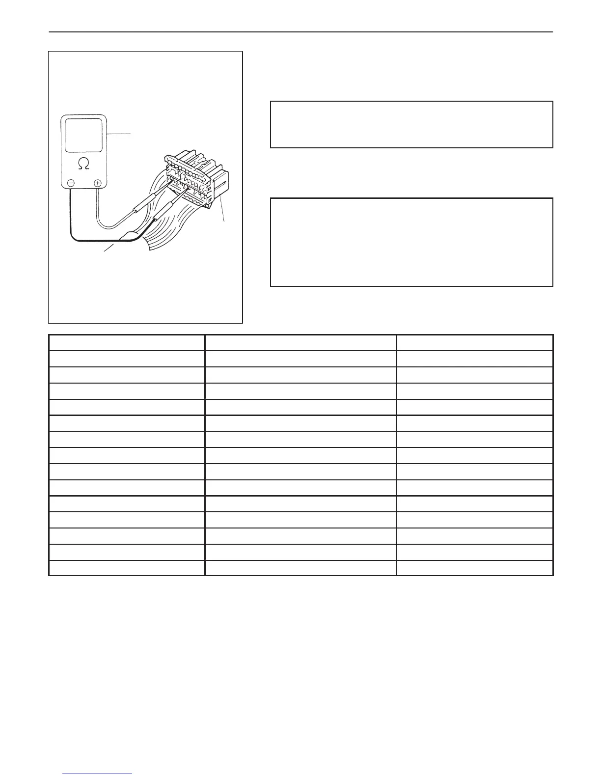
1. ECM (PCM)
coupler disconnected
2. Ohmmeter
RESISTANCE CHECK
1) Disconnect ECM (PCM) couplers from ECM (PCM) with ignition
switch OFF.
CAUTION:
Never touch terminals of ECM (PCM) itself or connect
voltmeter or ohmmeter.
2) Check resistance between each terminal of couplers discon-
nected.
CAUTION:
D Be sure to connect ohmmeter probe from wire harness
side of coupler.
D Be sure to turn OFF ignition switch for this check.
D Resistance in table below represents that when parts
temperature is 20_C (68_F).
TERMINALS CIRCUIT STANDARD RESISTANCE
C01-8 to C03-20 H02S-1 heater 11.7 – 14.3 Ω
C02-19 to C03-20 H02S-2 heater 11.7 – 14.3 Ω
C02-12 to C02-2/15 Fuel injector 2.4 – 3.6 Ω
C02-7 to C02-2/15 EVAP canister purge valve 30 – 34 Ω
C02-21 to C03-20 Fuel pump relay 100 – 120 Ω
C02-16 to C02-2/15 ISC actuator relay 100 – 120 Ω
C02-25 to C02-2/15 EFE heater relay 100 – 120 Ω
C02-8 to Body ground Shift solenoid-B 8 – 20 Ω
C02-9 to Body ground Shift solenoid-A 8 – 20 Ω
C02-20 to C02-2/15 Radiator fan control relay 100 – 120 Ω
C02-22 to C02-14 Main relay 100 – 120 Ω
C02-1 to Body ground Ground Continuity
C02-13 to Body ground Ground Continuity
C02-26 to Body ground Ground Continuity