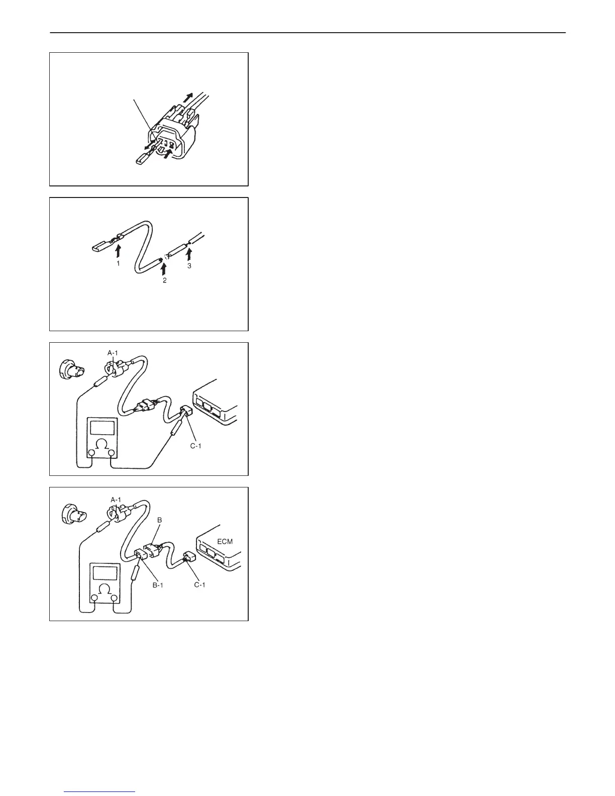
1. Looseness of crimping
2. Open
3. Thin wire (single strand of wire)
Check contact tension by
inserting and removing just
for once
GENERAL INFORMATION 0A-13
3) Using a test male terminal, check both terminals of the circuit be-
ing checked for contact tension of its female terminal.
Check each terminal visually for poor contact (possibly caused
by dirt, corrosion, rust, entry of foreign object, etc.).
At the same time, check to make sure that each terminal is
locked in the connector fully.
4) Using continuity check or voltage check procedure described in
the following page, check the wire harness for open circuit and
poor connection with its terminals. Locate abnormality, if any.
Continuity Check
1) Measure resistance between connector terminals at both ends
of the circuit being checked (between A-1 and C-1 in the figure).
If no continuity is indicated (infinity or over limit), that means that
the circuit is open between terminals A-1 and C-1.
2) Disconnect the connector included in the circuit (connector-B in
the figure) and measure resistance between terminals A-1 and
B-1.
If no continuity is indicated, that means that the circuit is open
between terminals A-1 and B-1. If continuity is indicated, there
is an open circuit between terminals B-1 and C-1 or an ab-
normality in connector-B.
Voltage Check
If voltage is supplied to the circuit being checked, voltage check can
be used as circuit check.
1) With all connectors connected and voltage applied to the circuit
being checked, measure voltage between each terminal and
body ground.