6-40 ENGINE GENERAL INFORMATION AND DIAGNOSIS (TBI FOR G10)
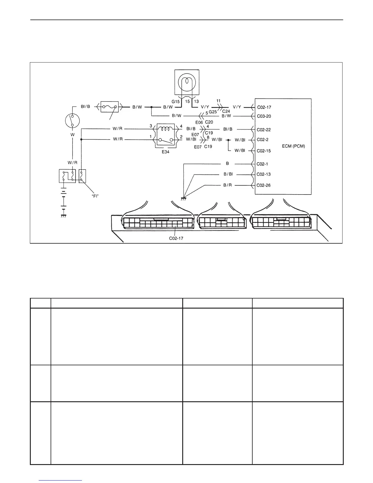
“IG COIL METER”
Main relay
Ignition switch
In fuse
Malfunction indicator lamp in combination meter
TABLE A-1 MALFUNCTION INDICATOR LAMP CIRCUIT CHECK – LAMP DOES
NOT COME “ON” AT IGNITION SWITCH ON (BUT ENGINE AT STOP)
CIRCUIT DESCRIPTION
When the ignition switch is turned ON, ECM (PCM) causes the main relay to turn ON (close the contact point).
Then, ECM (PCM) being supplied with the main power, turns ON the malfunction indicator lamp (MIL). When the
engine starts to run and no malfunction is detected in the system, MIL goes OFF but if a malfunction was or is de-
tected, MIL remains ON even when the engine is running.
INSPECTION
STEP ACTION YES NO
1 MIL Power Supply Check
1) Turn ignition switch ON.
Do other indicator/warning lights in
combination meter comes ON?
Go to Step 2. “IG COIL METER” fuse blown,
main fuse blown, ignition
switch malfunction, “B/W”
circuit between “IG COIL
METER” fuse and
combination meter or poor
coupler connection at
combination meter.
2 ECM (PCM) Power and Ground Circuit
Check
Does engine start?
Go to Step 3. Go to TABLE A-3 ECM (PCM)
POWER AND GROUND
CIRCUIT CHECK.
If engine is not cranked, go to
DIAGNOSIS in SECTION 8A.
3 MIL Circuit Check
1) Turn ignition switch OFF and disconnect
connectors from ECM (PCM).
2) Check for proper connection to ECM
(PCM) at terminal C02-17.
3) If OK, then using service wire, ground
terminal C02-17 in connector
disconnected.
Does MIL turn on at ignition switch ON?
Substitute a known-
good ECM (PCM) and
recheck.
Bulb burned out or “V/Y” wire
circuit open.