Main fuseIgnition switch
Main fuse
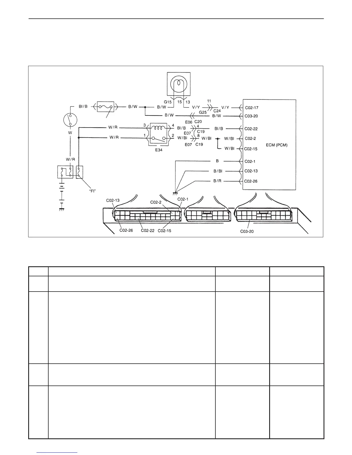
Malfunction indicator lamp in combination meter
Relay box
“IG COIL METER”
6-42 ENGINE GENERAL INFORMATION AND DIAGNOSIS (TBI FOR G10)
TABLE A-3 ECM (PCM) POWER AND GROUND CIRCUIT CHECK – MIL
DOESN’T LIGHT AT IGNITION SWITCH ON AND ENGINE DOESN’T
START THOUGH IT IS CRANKED UP
CIRCUIT DESCRIPTION
When the ignition switch tuned ON, the main relay turns ON (the contact point closes) and the main power is sup-
plied to ECM (PCM).
INSPECTION
STEP ACTION YES NO
1 Main Relay Operating Sound Check
Is operating sound of main relay heard at ignition switch ON?
Go to Step 5. Go to Step 2.
2 Main Relay Check
1) Turn OFF ignition switch and remove main relay (1).
2) Check for proper connection to main relay (1) at terminal
3 and 4.
3) Check resistance between each two terminals. See Fig. 1
and 2.
Between terminals 1 and 2: Infinity
Between terminals 3 and 4: 100 – 120 Ω
4) Check that there is continuity between terminals 1 and 2
when battery is connected to terminals 3 and 4. See Fig. 3.
Is main relay in good condition?
Go to Step 3. Replace main
relay.
3 Fuse Check
Is main “FI” fuse in good condition?
Go to Step 4. Check for short in
circuits connected
to this fuse.
4 ECM (PCM) Power Circuit Check
1) Turn OFF ignition switch, disconnect connectors from ECM
(PCM) and install main relay.
2) Check for proper connection to ECM (PCM) at terminals
C03-20, C02-2, C02-15 and C02-22.
3) If OK, then measure voltage between terminal C03-20 and
ground, C02-22 and ground with ignition switch ON.
Is each voltage 10 – 14 V?
Go to Step 5. “B/W”, “W/R” or
“Bl/B” circuit
open.