6-34 ENGINE GENERAL INFORMATION AND DIAGNOSIS (TBI FOR G10)
1. ECM (PCM)
2. ECM (PCM) couplers
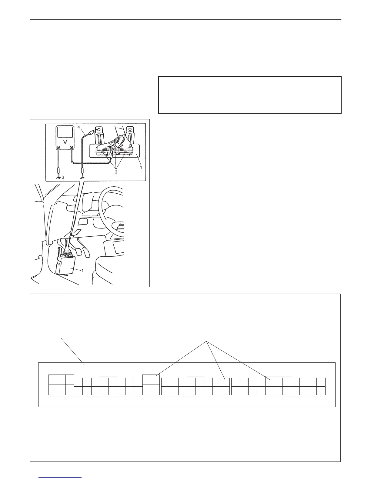
(Viewed from harness side)
1. ECM (PCM)
2. Couplers
3. Body ground
4. Service wire
16
C03C02 C01
1
2
12
3
456
7
8
9101112
34567
8
12
345678910
111213
12
131415
1617
18
19
202122910
1112
131415
1415
1617
181920212223
24
2526
INSPECTION OF ECM (PCM) AND ITS
CIRCUITS
ECM (PCM) and its circuits can be checked at ECM (PCM) wiring
couplers by measuring voltage and resistance.
CAUTION:
ECM (PCM) cannot be checked by itself. It is strictly prohib-
ited to connect voltmeter or ohmmeter to ECM (PCM) with
coupler disconnected from it.
Voltage Check
1) Remove ECM (PCM) (1) from body referring to Section 6E.
2) Check voltage at each terminal of couplers (2) connected.
NOTE:
As each terminal voltage is affected by the battery voltage,
confirm that it is 11 V or more when ignition switch is ON.