ENGINE GENERAL INFORMATION AND DIAGNOSIS (TBI FOR G10) 6-35
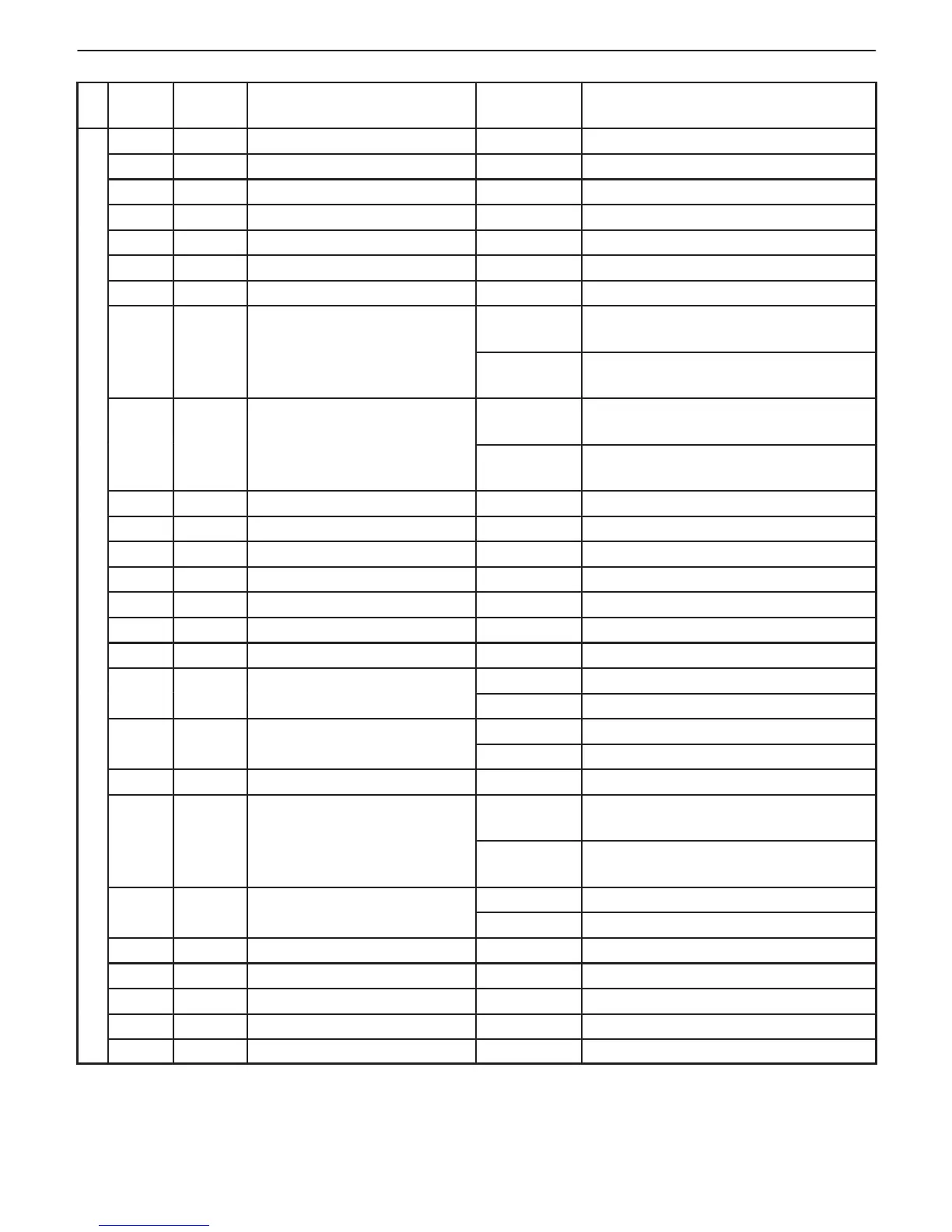
CONNECTOR “C02”
TER-
MINAL
WIRE
COLOR
CIRCUIT
STANDARD
VOLTAGE
CONDITION
1 B ECM (PCM) ground – –
2 W/Bl Power source 10 – 14 V Ignition switch ON
3 — Blank — —
4 — Blank — —
5 — Blank — —
6 — Blank — —
7 R/G EVAP canister purge valve 10 – 14 V Ignition switch ON
0 V
Ignition switch ON, selector lever at “P”
range
10 – 14 V
Ignition switch ON, selector lever at “D”
range
0 V
Ignition switch ON, selector lever at “P”
range
10 – 14 V
Ignition switch ON, selector lever at “D”
range
10 Or Igniter (IGT) — —
11 Gr/Y ISC actuator — —
12 Y/B Fuel injector 10 – 14 V Ignition switch ON
13 B/Bl Ground for injector — —
14 W Power source for back-up 10 – 14 V Ignition switch ON and OFF
15 W/Bl Power source 10 – 14 V Ignition switch ON
16 Gr /B ISC actuator relay 0.3 – 1.0 V Ignition switch ON
Malfunction indicator lam
p
0.2 – 2.0 V Ignition switch ON
10 – 14 V When engine running
Immobilizer indicator lam
p
0.2 – 2.0 V Ignition switch ON
10 – 14 V When engine running at idle
19 Lg/B Heater of H02S-2 10 – 14 V Ignition switch ON
Radiator fan control relay
10 – 14 V
Ignition switch ON, Engine coolant
temp: Below 91.5_C (197_F)
0.3 – 1.0 V
Ignition switch ON, Engine coolant
temp: 96.0_C (205_F) or higher
0.3 – 1.3 V For 2 seconds after ignition switch ON
10 – 14 V After the above time
22 Bl/B Main relay 0.4 – 1.5 V Ignition switch ON
23 – Blank — —
24 Gr/R ISC actuator — —
25 Y/R EFE heater relay 10 – 14 V Ignition switch ON
26 B/R Ground for injector — —