ENGINE GENERAL INFORMATION AND DIAGNOSIS (TBI FOR G10) 6-37
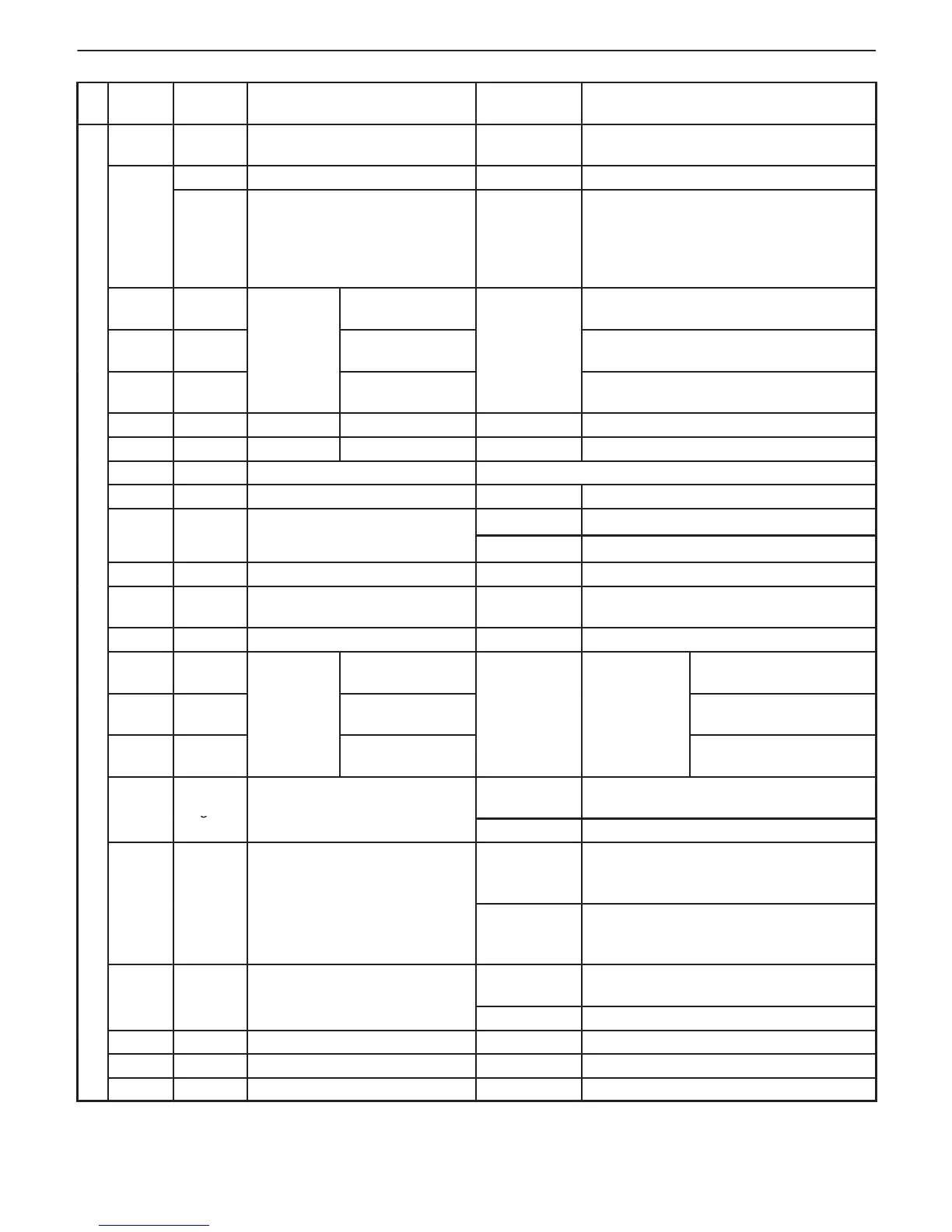
CONNECTOR “C03”
TER-
MINAL
WIRE
COLOR
CIRCUIT
STANDARD
VOLTAGE
CONDITION
1 V/W
Data link connector
(SUZUKI serial data line)
4 – 6 V Ignition switch ON
Bl Vehicle speed sensor (+) (A /T) 0.4 – 0.8 V Ignition switch ON
2
Y/G Vehicle speed sensor (M/ T)
Indicator
deflection
repeated
0 V and
4 – 6 V
Ignition switch ON
Front left tire turned slowly with front
right tire locked
3 G
Transmis-
“2” range
Ignition switch ON, Selector lever at “2”
range
4 Or/ Y
s
“N” range
10 – 14 V
Ignition switch ON, Selector lever at “N”
range
5 Or/ B
(A/T only).
“P” range
Ignition switch ON, Selector lever at “P”
range
6 — Blank – —
7 — Blank – —
8 R Heated oxygen sensor-2 Refer to DTC flow chart
9 — — — —
Ignition switch ON fuel tank fully filled
Fuel level sensor (gauge)
Ignition switch ON fuel tank em
11 — Blank — —
12 R/G
Data link connector
(OBD serial data line)
10 – 14 V Ignition switch ON
13 P Vehicle speed sensor (–) (A/T) 0.4 – 0.8 V Ignition switch ON
14 G/Bl
Transmis-
“L” range
Selector lever at “L”
range
15 G/R
s
“D” range
10 – 14 V
Ignition
switch ON
Selector lever at “D”
range
16 R
(A/T)
“R” range
Selector lever at “R”
range
17 L
/R
A/C ON (output) signal for A/C
0 – 1 V
While engine running and A/ C not
operating
10 – 14 V While engine running and A/ C operating
0 –1 V
Ignition switch ON
Headlight, small light, heater fan and
rear window defogger turned OFF
10 – 14 V
Ignition switch ON
Headlight, small light, heater fan and
rear window defogger turned ON
19 Bl/R
A/C (input) signal for A/C
10 – 14 V
While engine running and A/ C not
operating
0 – 0.6 V While engine running and A/C operating
20 B/W Ignition switch 10 – 14 V Ignition switch ON
21 — Blank — —
22 — Blank — —