ENGINE GENERAL INFORMATION AND DIAGNOSIS (TBI FOR G10) 6-51
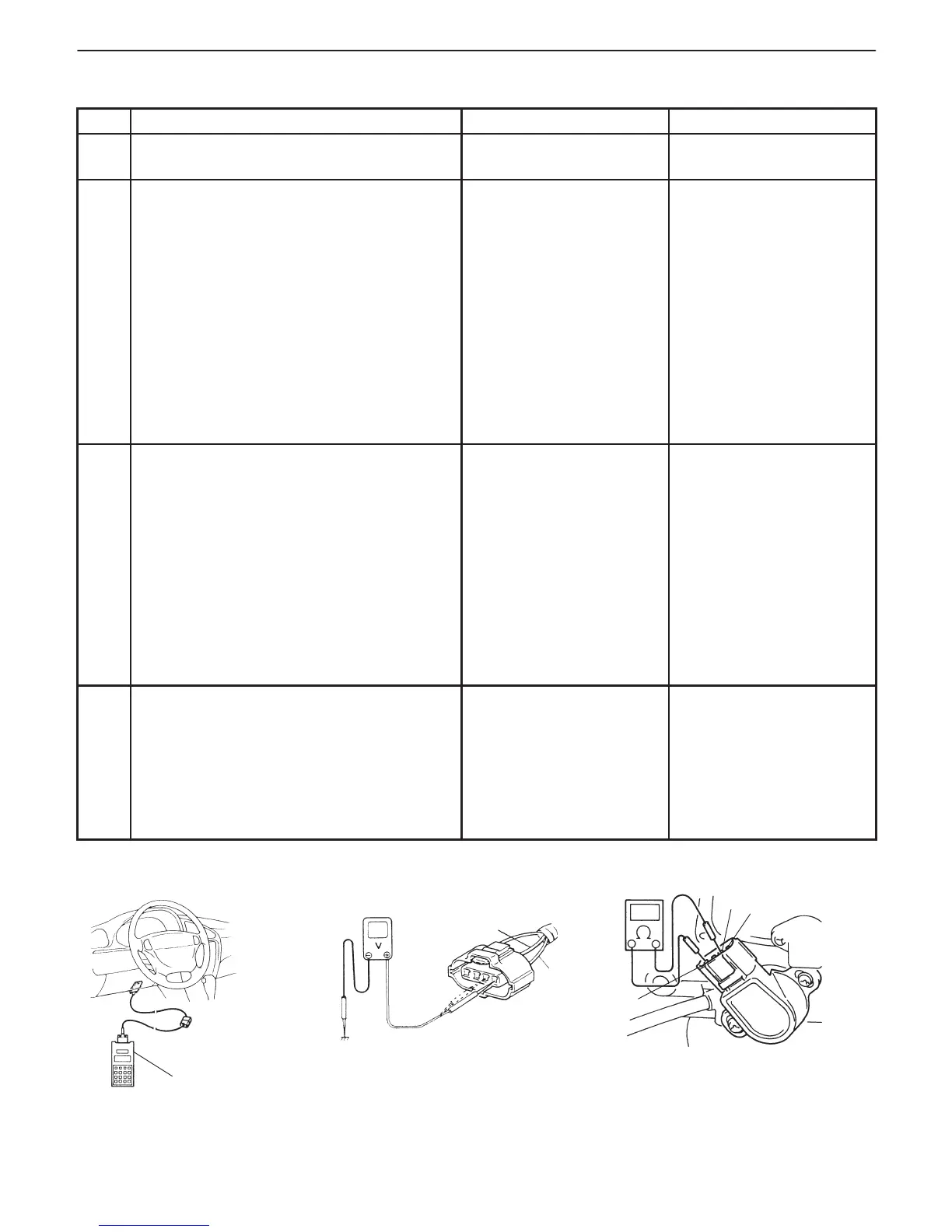
Fig. 1 for Step 2 Fig. 2 for Step 3 Fig. 3 for Step 4
Scan tool
“Lg”
“Lg/W”
“3”
“4”
“1”
INSPECTION
STEP ACTION YES NO
1 Was “ENGINE DIAG. FLOW TABLE”
performed?
Go to Step 2. Go to “ENGINE DIAG.
FLOW TABLE”.
2 Check TP Sensor and Its Circuit.
1) Connect scan tool to DLC with ignition
switch OFF and then turn ignition switch
ON.
2) Check throttle valve opening percentage
displayed on scan tool. See Fig. 1.
Is it displayed 2% or less?
3) Check throttle valve opening percentage
displayed on scan tool while opening
throttle valve from idle position to full open
position. See Fig. 1.
Is it displayed 96% or higher?
Go to Step 3. Intermittent trouble.
Check for intermittent
referring to “Intermittent
and Poor Connection” in
Section 0 A.
3 Check Wire Harness.
1) Disconnect connector from TP sensor
with ignition switch OFF.
2) Check for proper connection to TP sensor
at “Lg”, “Lg/W” and “G” wire terminal.
3) If OK, then with ignition switch ON, check
voltage at each of “Lg” and “Lg/W” wire
terminals. See Fig. 2.
Is voltage about 4 – 6 V at each terminal?
Go to Step 4. “Lg” wire open, “Lg”
wire shorted to ground
circuit or power circuit or
“G” wire, “Lg/W” wire
open or shorted to ground
circuit or poor C01-1 or
C01-6 connection.
If wire and connection are
OK, substitute a known-
good ECM (PCM) and
recheck.
4 Check TP Sensor.
1) Check resistance between terminals of
TP sensor. See Fig. 3.
Between 1 and 4: 2.87 – 5.33 kΩ
Between 1 and 3: 100 Ω – 20 kΩ, varying
according to throttle valve opening.
Are measured values within specifications?
“G” wire open or poor
C01–9 connection.
If wire and connection are
OK, substitute a known-
good ECM (PCM) and
recheck.
Replace TP sensor.