ENGINE GENERAL INFORMATION AND DIAGNOSIS (TBI FOR G10) 6-73
INSPECTION
STEP ACTION YES NO
1 Was “ENGINE DIAG. FLOW TABLE” performed? Go to Step 2. Go to “ENGINE DIAG.
FLOW TABLE”.
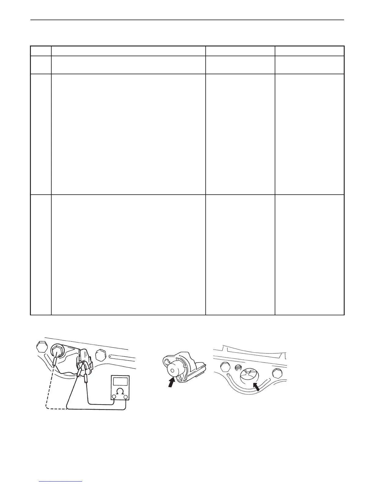
2 Check CKP Sensor for Resistance.
1) Disconnect CKP sensor connector with ignition
switch OFF.
2) Then check for proper connection to CKP sensor
at “W/B” and “W/R” wire terminals.
3) If OK, measure sensor resistance between
terminals. See Fig. 1.
CKP sensor resistance: 360 – 460 Ω
at 20_C, (68_F)
4) Measure resistance between each terminal and
ground.
Insulation resistance: 1 MΩ or more.
Were measured resistance valves in step 3) and 4)
as specified?
Go to Step 3. Replace CKP sensor.
3 Check visually CKP sensor and pulley for the
following. See Fig. 2.
D Damage
D No foreign material attached.
D Correct installation.
Are they in good condition?
“W/B” or “W/R” wire
open or shorted to
ground, or poor
connection at C01-3
or C01-11.
If wire and connection
are OK, intermittent
trouble or faulty ECM
(PCM).
Recheck for
intermittent referring
to “Intermittent and
Poor Connection” in
Section 0A.
Clean, repair or
replace.
Fig. 1 for Step 2 Fig. 2 for Step 3