ENGINE GENERAL INFORMATION AND DIAGNOSIS (TBI FOR G10) 6-75
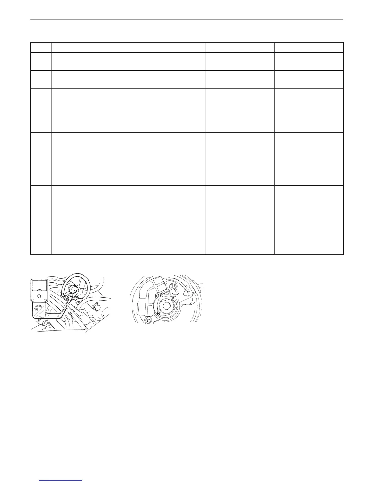
Fig. 1 for Step 3 Fig. 2 for Step 5
“a”: Air gap
INSPECTION
STEP ACTION YES NO
1 Was “ENGINE DIAG. FLOW TABLE” performed? Go to Step 2. Go to “ENGINE DIAG.
FLOW TABLE”.
2 Is DTC P1500 (Engine starter signal circuit
malfunction) detected?
Go to DTC P1500
Diag. Flow Table.
Go to Step 3.
3 Check CMP Sensor for Resistance.
1) Measure resistance of CMP sensor by referring to
“CMP SENSOR (PICK UP COIL) RESISTANCE”
in SECTION 6F.
Is resistance within specified value?
Go to Step 4. Faulty CMP sensor.
4 Check Wire Harness.
1) With ignition switch at OFF position, disconnect
ECM (PCM) electrical connectors.
2) Measure resistance from terminal “C01-2” to
“C01-10” of ECM (PCM) connector. See Fig. 1.
Is resistance within 185 – 275 Ω at 20_C (68_F)?
Go to Step 5. “W” or “Or” wire open
or short.
Poor connection of
CMP sensor
connector terminal.
5 Check Air Gap Between Rotor Tooth and Sensor. See
Fig. 2.
1) Remove Distributor cap.
2) Visually inspect CMP sensor signal rotor for
damage.
3) Measure air gap by referring “SIGNAL ROTOR
AIR GAP” in Section 6F.
Was any damage found?
Faulty CMP sensor
signal rotor.
Poor connection of
ECM (PCM)
connector terminal.
If OK, substitute a
known-good ECM
(PCM) and recheck
CMP.
 Loading...


