ENGINE GENERAL INFORMATION AND DIAGNOSIS (TBI FOR G10) 6-81
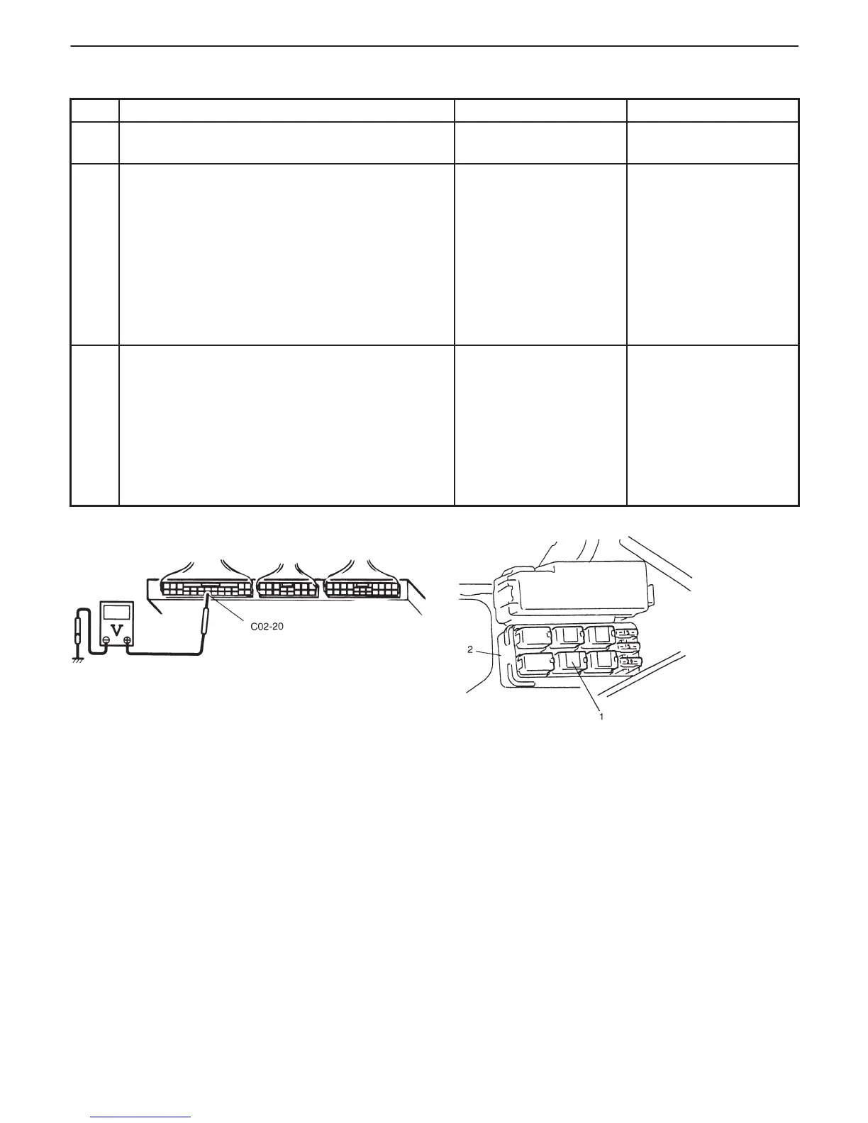
Fig. 1 for Step 2 Fig. 2 for Step 3
1. Radiator fan relay
2. Relay box
INSPECTION
STEP ACTION YES NO
1 Was “ENGINE DIAG. FLOW TABLE” performed? Go to Step 2. Go to “ENGINE DIAG.
FLOW TABLE”.
2 Check Radiator Cooling Fan Relay and Its Circuit.
1) Turn ignition switch ON.
2) Check for voltage at terminal C02-20 of ECM
(PCM) connector connected, under following
condition. See Fig. 1.
When engine coolant temp. is lower than
96_C, 205_F and A/C switch turns OFF:
10 – 14 V
Is voltage as specified?
Intermittent trouble or
faulty ECM (PCM).
Check for intermittent
referring to “Intermittent
and Poor Connection”
in Section 0A.
Go to Step 3.
3 Check Radiator Fan Control Relay.
1) Turn ignition switch OFF and remove radiator
fan relay.
2) Check for proper connection to the relay at
“B/W” and “Bl” wire terminals.
3) If OK, then measure resistance between
terminals a and b. See Fig. 2.
Is it 100 – 120 Ω?
“B/W” or “Bl” circuit
open or short.
If wires and connections
are OK, substitute a
known-good ECM (PCM)
and recheck.
Replace radiator fan
relay.

 Loading...


