ENGINE GENERAL INFORMATION AND DIAGNOSIS (TBI FOR G10) 6-83
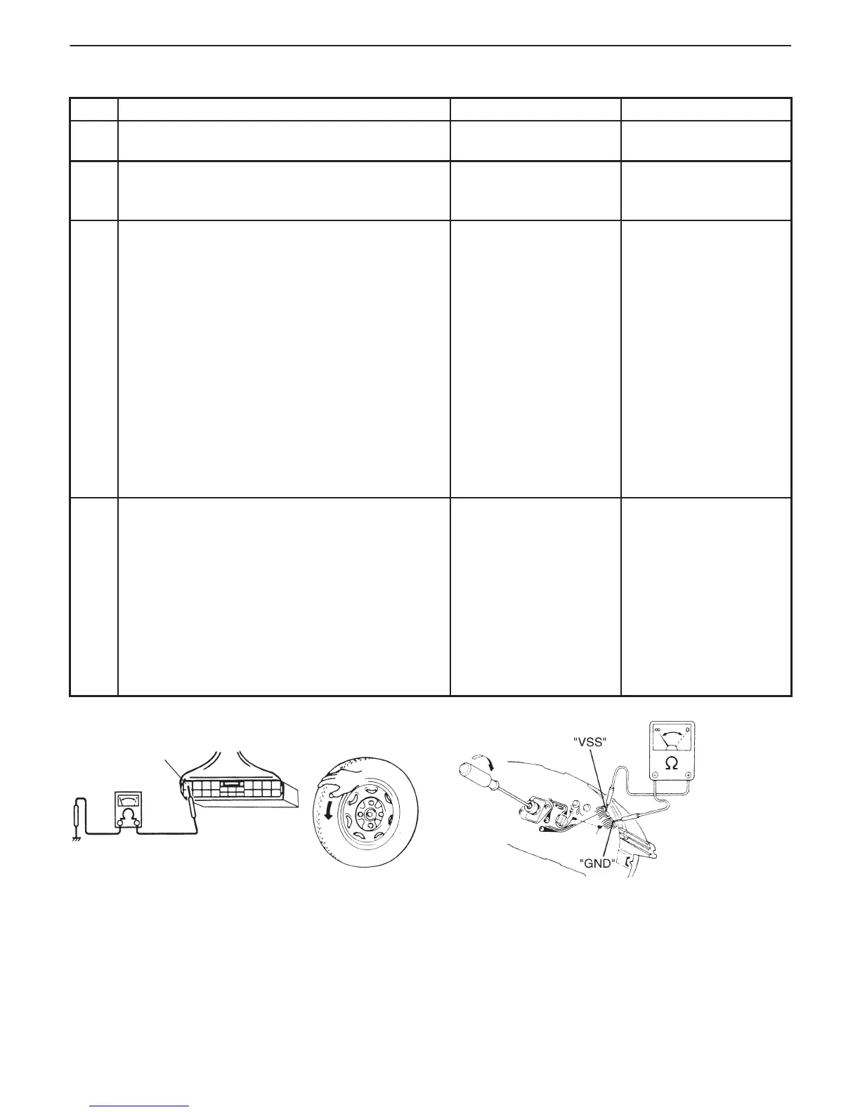
Fig. 1 for Step 3 Fig. 2 for Step 4
C03-2
INSPECTION
STEP ACTION YES NO
1 Was “ENGINE DIAG. FLOW TABLE” performed? Go to Step 2. Go to “ENGINE DIAG.
FLOW TABLE”.
2 Does speedometer indicate vehicle speed? Go to Step 3. Speedometer cable
disconnected or
broken.
3 Check VSS and Its Circuit.
1) Disconnect ECM connector with ignition
switch OFF.
2) Check for proper connection to ECM at
terminal C03-2.
3) If OK, then connect ohmmeter between
terminal C03-2 of ECM connector and body
ground. See Fig. 1.
4) Hoist front end of vehicle and lock front right
tire.
5) Turn front left tire slowly.
Does ohmmeter indicator deflect between
0 and ∞ a few times while tire is turned one
revolution?
Intermittent trouble or
faulty ECM.
Check for intermittent
referring to “Intermittent
and Poor Connection”
in Section 0A.
Go to Step 4.
4 Check VSS.
1) Remove combination meter.
2) Connect ohmmeter between “VSS” terminal
(No.10) and “GND” (No.4) terminal of
combination meter and turn cable joint of
speedometer with a screwdriver. Ohmmeter
indicator should move back and forth between
0 (zero) and ∞ (infinity) 4 times while cable joint
is turned one full revolution. See Fig. 2.
Is it in good condition?
“Y/G” or “B/Bl” wire
open or short, or poor
connector connection.
Replace VSS.