ENGINE GENERAL INFORMATION AND DIAGNOSIS (TBI FOR G10) 6-85
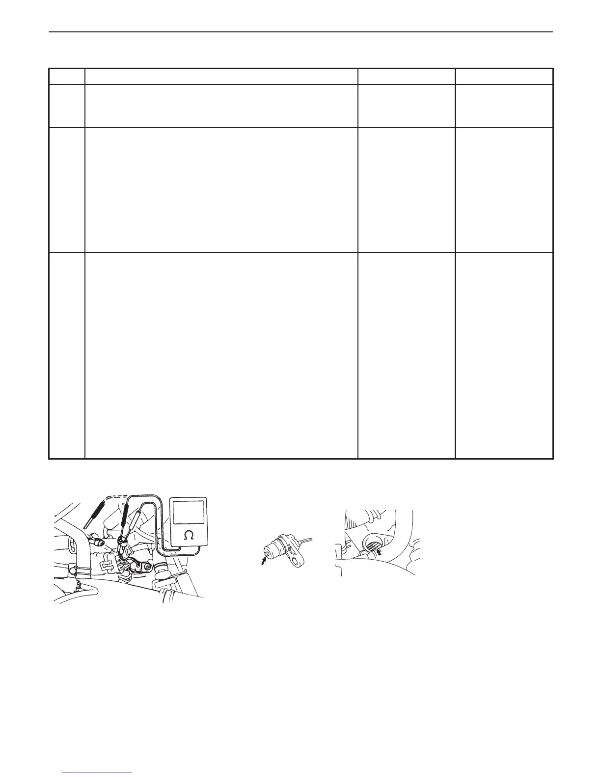
Fig. 1 for Step 2 Fig. 2 for Step 3
INSPECTION
STEP ACTION YES NO
1 Was “ENGINE DIAG. FLOW TABLE” performed? Go to Step 2. Go to “ENGINE
DIAG. FLOW
TABLE”.
2 Check VSS for Resistance.
1) Disconnect VSS connection with ignition switch OFF.
2) Check for proper connection to VSS at “Bl” and “P” wire
terminals.
3) If OK, then check resistance of VSS. See Fig. 1.
Resistance between terminals : 100 – 300 Ω
Resistance between terminal
and transmission : 1 MΩ or more
Are check result satisfactory?
Go to Step 3. Replace VSS.
3 Check Visually VSS and Counter Shaft Gear for the
Following. See Fig. 2.
D No damage
D No foreign material attached
D Correct installation
Are they in good condition?
“BI” or “P” wire
open or shorted to
ground or poor
C03-2 or C03-13
connection. If
wires and
connections are
OK, intermittent
trouble or faulty
PCM. Check for
intermittent
referring to
“Intermittent and
Poor Connection”
in Section 0A.
Clean, repair or
replace.