ENGINE GENERAL INFORMATION AND DIAGNOSIS (TBI FOR G10) 6-87
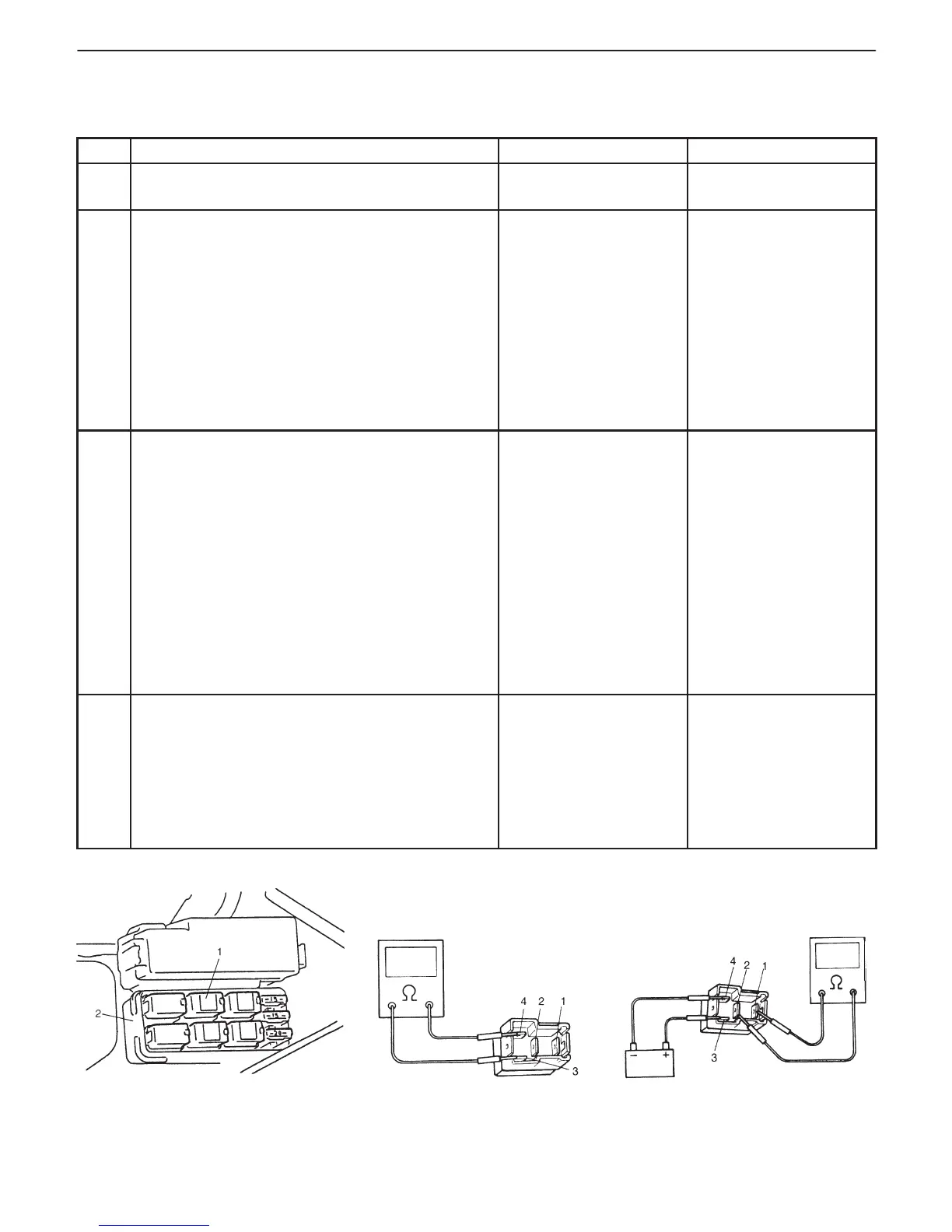
Fig. 1 for Step 3 Fig. 2 for Step 3 Fig. 3 for Step 3
1. ISCA relay
2. Relay box
DTC P0505
INSPECTION
STEP ACTION YES NO
1 Was “ENGINE DIAG. FLOW TABLE” performed? Go to Step 2. Go to “ENGINE DIAG.
FLOW TABLE”.
2 Check Idle Control System.
1) Connect SUZUKI scan tool to DLC with ignition
switch OFF, set parking brake and block drive
wheels.
2) Warm up engine to normal operating
temperature.
3) Clear DTC and select “MISC TEST” mode on
SUZUKI scan tool.
Is it possible to control (increase and reduce)
engine idle speed by using SUZUKI scan tool?
Check TP sensor (Go to
DTC P0121 Flow Table)
If TP sensor is OK,
intermittent trouble or
faulty ECM (PCM).
Check for intermittent
referring to “Intermittent
and Poor Connection”
in Section 0A.
Go to Step 3.
3 Check ISC Relay.
1) Ignition switch OFF and remove ISC relay
(“ISCA”).
2) Check for proper connection to ISC relay at
terminals 3 and 4.
3) Check resistance between each two terminals.
Between terminals 1 and 2: Infinity
Between terminals 3 and 4: 100 – 120 Ω
4) Check that there is continuity between
terminals 1 and 2 when battery is connected to
terminals 3 and 4.
Is ISC relay in good condition?
Go to Step 4. Replace ISC relay.
4 Check Idle Speed Control Actuator.
1) Check ISC actuator operation by referring to
ISC ACTUATOR INSPECTION in Section 6.
Is it good condition?
Check “Gr/B”, “Gr/Y”,
“Gr” and “Gr/R” circuit
for open and short.
If wires and connections
are OK, substitute a
known-good ECM
(PCM) and recheck.
Replace throttle lower
body with ISC actuator.