ENGINE GENERAL INFORMATION AND DIAGNOSIS (SFI FOR G13) 6-1-45
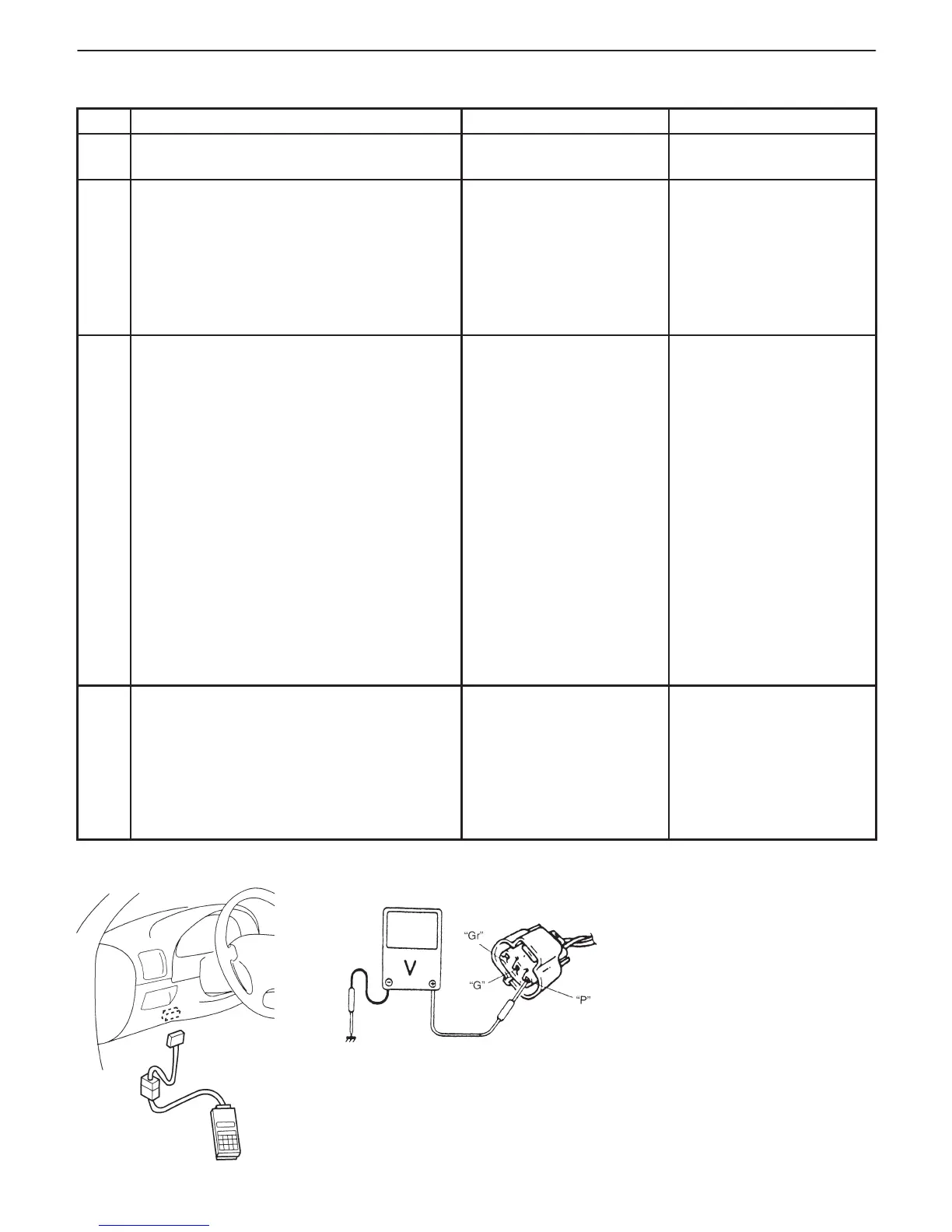
Fig. 1 for Step 2 Fig. 2 for Step 3
INSPECTION
STEP ACTION YES NO
1 Was “ENGINE DIAG. FLOW TABLE”
performed?
Go to Step 2. Go to “ENGINE DIAG.
FLOW TABLE”.
2 Check MAP Sensor and Its Circuit.
1) Connect scan tool to DLC with ignition
switch OFF.
2) Turn ignition switch ON.
3) Check intake manifold pressure.
See Fig. 1.
Is it 114.7 kPa or more or 4.9 kPa or less?
Go to Step 3. Intermittent trouble.
Check for intermittent
referring to
“INTERMITTENT AND
POOR CONNECTION” in
Section 0A.
3 Check Wire Harness.
1) Disconnect MAP sensor connector with
ignition switch OFF.
2) Check for proper connection of MAP
sensor at “Gr” and “G” wire terminals.
3) If OK, then with ignition switch ON, check
voltage at each of “P” and “Gr” wire
terminals. See Fig. 2.
Is voltage about 4 – 6 V at each terminal?
Go to Step 4. “P” wire open or shorted to
ground circuit or shorted to
power circuit, “Gr” wire
open or shorted to ground,
poor C03-5 connection or
C01-22 connection.
If wire and connection are
OK, confirm that MAP
sensor is normal and then
substitute a known-good
ECM (PCM) and recheck.
NOTE: When battery
voltage is applied to
“P” wire, it is possible
that MAP sensor is also
faulty.
4 Check MAP sensor according to “MAP
Sensor Individual Check” below.
Is it in good condition?
“P” wire shorted to “Gr”
wire, “G” wire open,
poor C01-10 connection.
If wire and connection are
OK, substitute a known-
good ECM (PCM) and
recheck.
Replace MAP sensor.