ENGINE GENERAL INFORMATION AND DIAGNOSIS (SFI FOR G13) 6-1-59
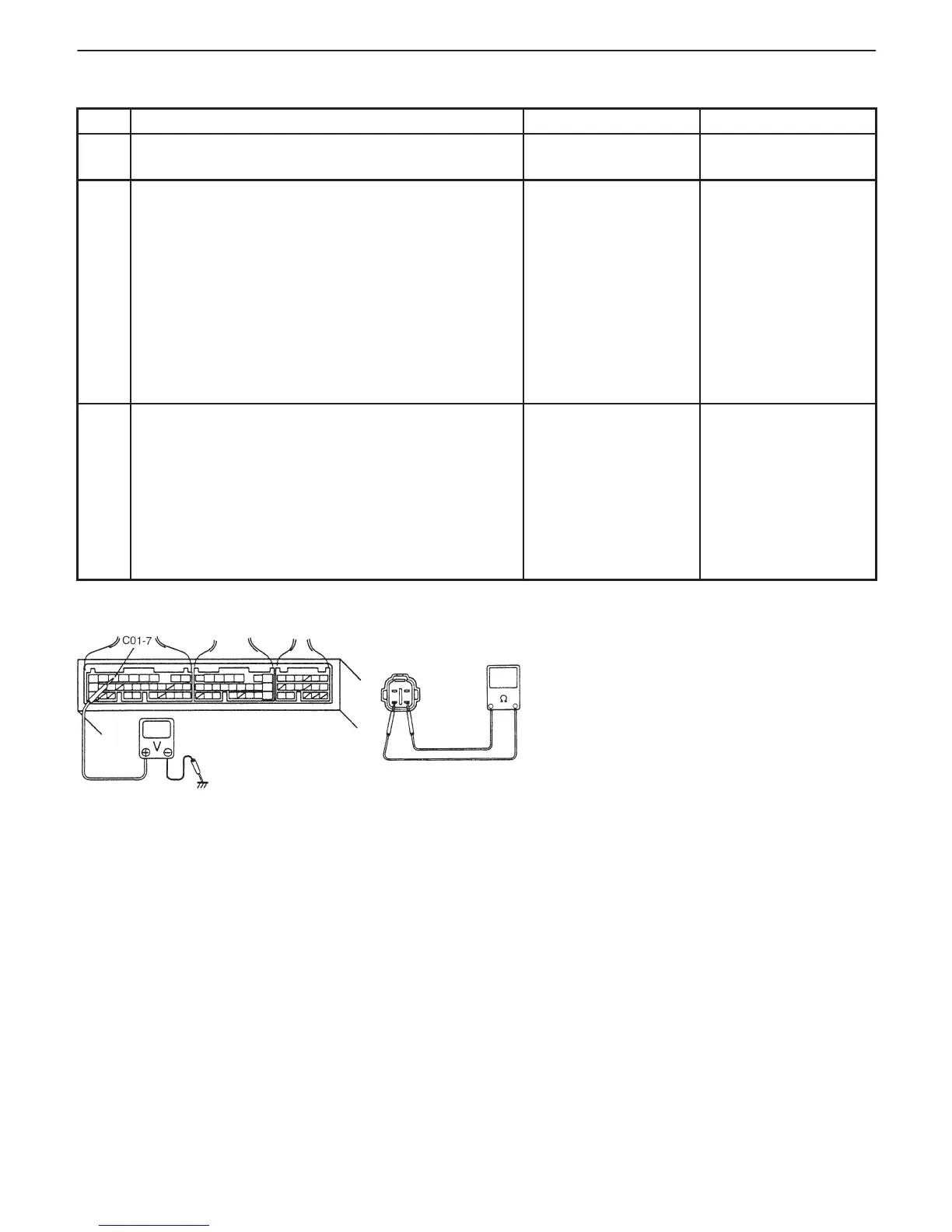
Fig. 1 for Step 2 Fig. 2 for Step 3
INSPECTION
STEP ACTION YES NO
1 Was “ENGINE DIAG. FLOW TABLE” performed? Go to Step 2. Go t o“ENGINE DIAG.
FLOW TABLE”.
2 Check Heater for Operation.
1) Check voltage at terminal C01-7. See Fig. 1.
2) Warm up engine to normal operating temperature.
3) Stop engine.
4) Turn ignition switch ON and Check voltage at
Intermittent trouble
Check for intermittent
referring to
“Intermittent and
Poor Connection”
Go to Step 3.
terminal C01-7. See Fig. 1. Voltage should be
over 10 V.
5) Start engine, run it at idle and check voltage at the
same terminal. Voltage should be below 1.9 V.
Are check results are specified?
in Section 0A.
3 Check Heater of Sensor-1.
1) Disconnect HO2S-1 coupler with ignition switch
OFF.
2) Check for proper connection to HO2S-1 at “B/W”
and “Bl” wire terminals.
3) If OK, then check heater resistance. See Fig. 2.
Is it 11.7 – 14.3 Ω at 20_C, 68_F?
“Bl” wire open or
shorted to ground or
poor connection at
C01-7. If wire and
connection are OK,
substitute a
known-good ECM
(PCM) and recheck.
Replace HO2S-1.
 Loading...


