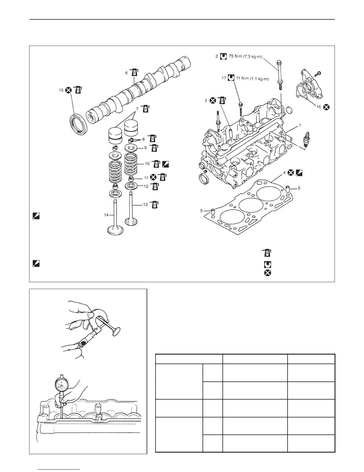
1. Cylinder head
2. Cylinder head bolt
3. Valve guide
4. Cylinder head gasket:
“TOP” mark provided on
gasket comes to crankshaft
pulley side, facing up
(toward cylinder head side).
5. Pin
6. Camshaft
7. Valve lash adjuster
8. Valve cotters
9. Valve spring retainer
10. Valve spring:
Be sure to position spring in place with
its bottom end (small-pitched) facing the
bottom (valve spring seat side).
11. Valve stem seal
12. Valve spring seat
13. Exhaust valve
14. Intake valve
15. Oil seal
16. Gasket
17. Camshaft housing bolt
: Tightening Torque
: Do not reuse
: Apply engine oil to sliding
: surfaces of each part.
ENGINE MECHANICAL (G10, 1-CAM 6-VALVES ENGINE) 6A-21
VALVES AND CYLINDER HEAD
INSPECTION
Valve Guides
Using a micrometer and bore gauge, take diameter readings on
valve stems and guides to check stem-to-guide clearance.
Be sure to take reading at more than one place along the length of
each stem and guide.
If clearance exceeds limit, replace valve and valve guide.
Item
Standard Limit
Valve stem
In
5.457 – 5.480 mm
(0.2148 – 0.2157 in.)
———
diameter
Ex
5.440 – 5.455 mm
(0.2142 – 0.2148 in.)
———
Valve guide
I.D.
In &
Ex
5.500 – 5.512 mm
(0.2165 – 0.2170 in.)
———
Stem-to-