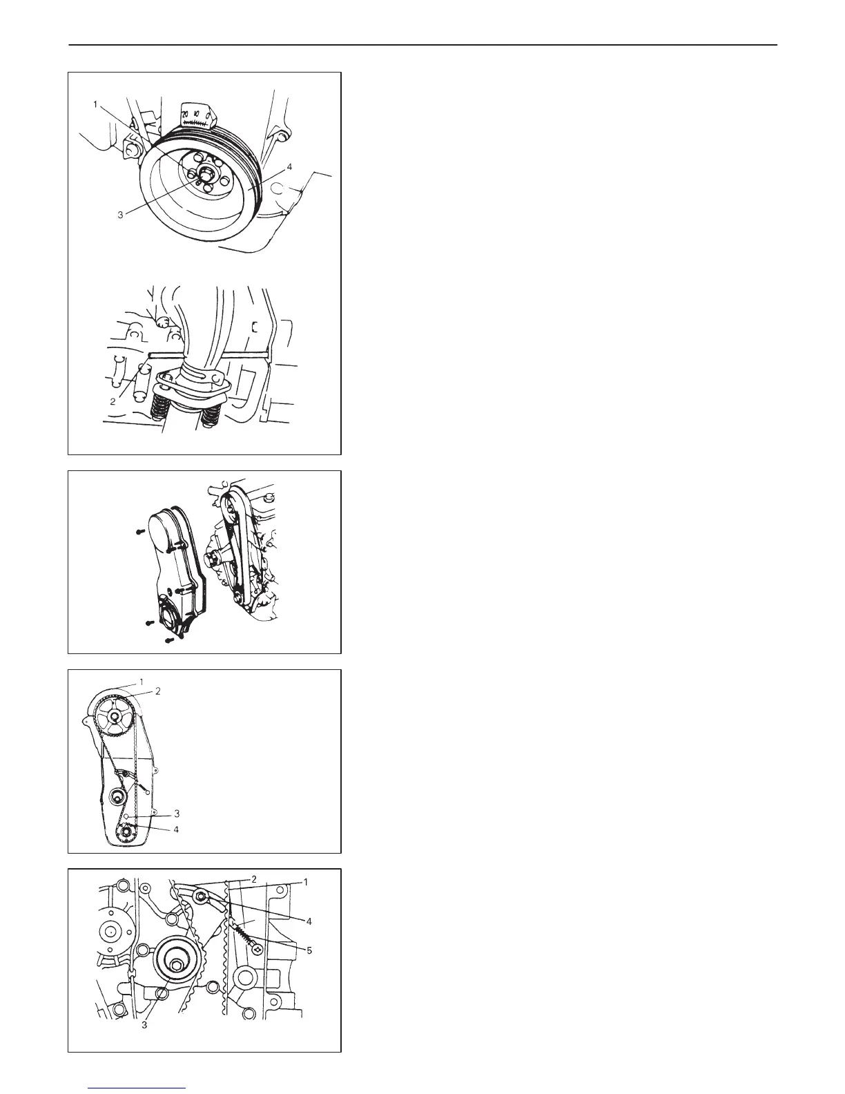
1. “V” mark on cylinder
head cover
2. Timing mark by “E” on
camshaft timing belt pulley
3. Arrow mark on oil
pump case
4. Punch mark on crankshaft
timing belt pulley
4. Tensioner stud
6. Damper
6
6A1-20 ENGINE MECHANICAL (G13B, 1-CAM 16-VALVES ENGINE)
8) Lock crankshaft inserting flat end rod or the like (2) between fly-
wheel ring gear and transmission case, after removing clutch
housing (torque converter housing for A/T) lower plate.
With crankshaft locked, remove crankshaft timing belt pulley
bolt (3).
9) Remove crankshaft pulley bolts (1).
10) Remove crankshaft pulley (4).
11) Install crankshaft timing belt pulley bolt temporarily to turn
crankshaft.
12) Release harness clamps.
13) Remove timing belt outside cover.
14) For installation of timing belt, align 4 timing marks as shown in
figure by turning crankshaft.
15) Remove timing belt tensioner (3), tensioner plate (2), tensioner
spring (5) and timing belt (1).

 Loading...


