IMMOBILIZER CONTROL SYSTEM 8G-3
Vehicle without monitor coupler
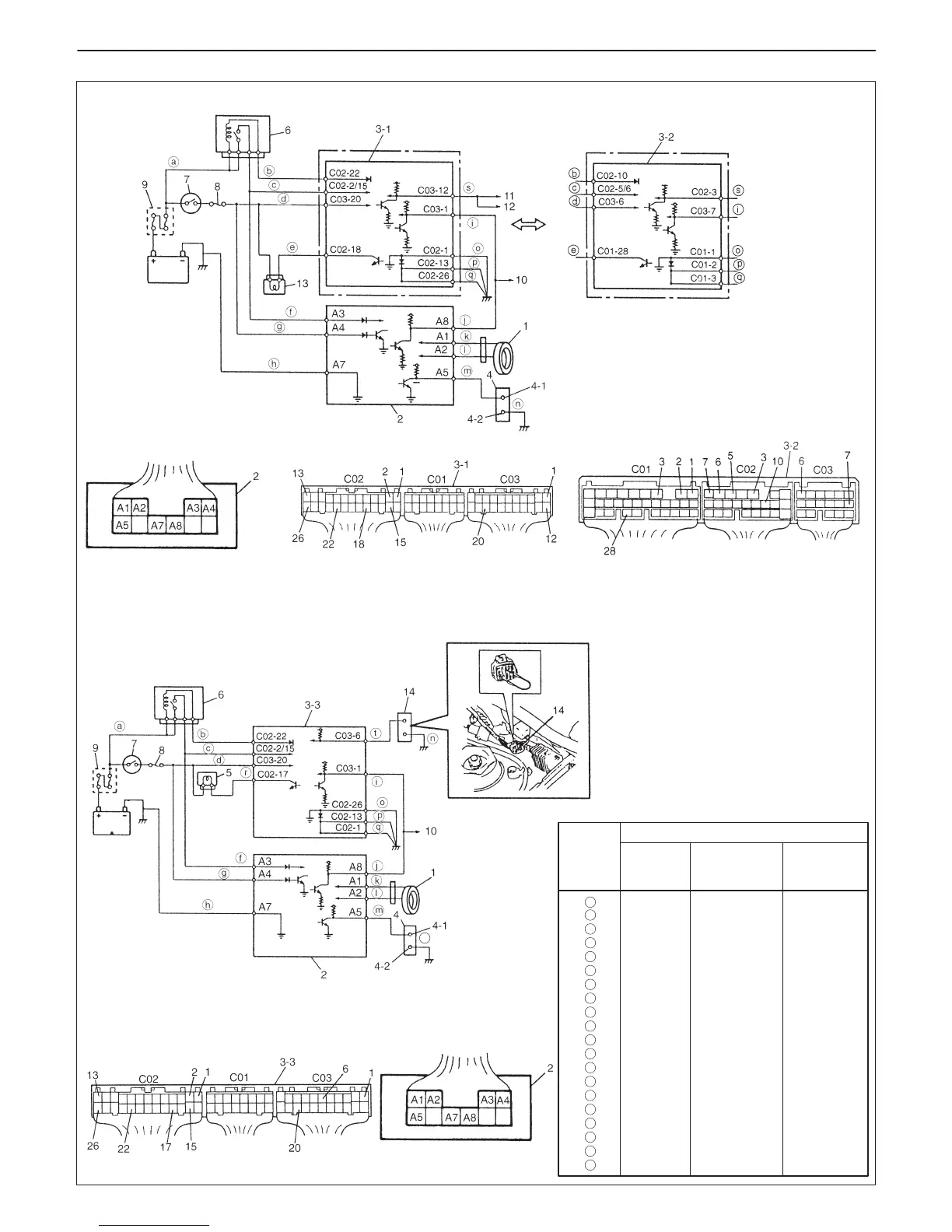
1. Coil antenna
2. Immobilizer Control Module
3-1. ECM (G10 engine)
3-2. ECM (G13 engine without monitor coupler)
3-3. ECM (G13 engine with monitor coupler)
4. Immobilizer diagnostic coupler
4-1. Diagnostic output terminal
4-2. Ground terminal
5. Malfunction indicator lamp
6. Main relay
7. Ignition switch
8. Fuse
9. Main fuse
10. To #9-pin in Data link connector
11. To #7-pin in Data link connector
12. To ABS control module
13. Immobilizer indicator lamp
(Vehicle not equipped with monitor coupler)
14. Monitor coupler (Vehicle not equipped
with immobilizer indicator lamp)
Vehicle with monitor coupler
G10 engine
G13 engine
G13B engine
n
W/R
Bl / B
W/Bl
B/W
V/G
W/Bl
B/W
B
V/W
V/W
P/B
P/Bl
P/G
B
B
B/Bl
B/R
–
R/G
–
W/R
Gr
R/B
B/W
V/G
W/Bl
B/W
B
Y/B
V/W
P/B
P/Bl
P/G
B
B
B/Or
B/Or
–
R/G
–
W/R
G/B
W/Bl
B/W
–
W/Bl
B/W
B
V/W
V/W
P/B
P/Bl
P/G
B
B/Bl
B/Bl
B/G
V
–
V/Y
WIRE
SYMBOL
G10 engine
G13 engine
without monitor
coupler
G13 engine
with monitor
coupler
WIRE COLOR
a
b
c
d
e
f
g
h
i
j
k
l
m
n
o
p
q
r
s
t