AMI CACE
Installation
A-96.250.871 / 120417 15
3. Installation
3.1. Installation Checklist Monitors
Check Instrument’s specification must conform to your AC power ratings.
Do not turn on power until instructed to do so.
On site require-
ments
100–240 VAC (± 10%), 50/60 Hz (± 5%) or 24 VDC, isolated
(±10%) power outlet with ground connection and 30 VA
For sample requirements see Instrument Specification, p. 12).
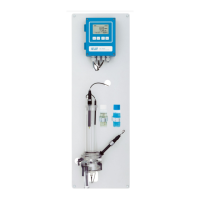
Installation
Mount the instrument in vertical position.
Display should be at eye level.
Remove the end caps from tubes 1, 2, 3, 5 and 10 and connect
the tubes according to Tube numbering, p. 43.
Connect sample inlet and outlet.
Electrical Wiring
Connect all external devices like limit switches, current loops and
pumps (see Connection Diagram, p. 20).
Connect power cord; do not switch on power yet!
Power-up
Open sample flow and wait until the instrument is completely
filled.
Check inlet pressure.
Switch on power.
Instrument
set-up
Program all sensor parameters (see Sensor parameters, p. 28).
If required activate calculations (see Calculations, p. 29).
Program all parameters for external devices (interface,
recorders, etc.).
Program all parameters for instrument operation (limits, alarms).
Program display screens.
Run-in period
Let the instrument run continuously for 1 h.