GB.COMPACTUT.170622
Registered design. The company reserves the right to make design changes without prior notice.
4 www.swegon.com
1
2
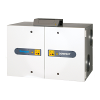
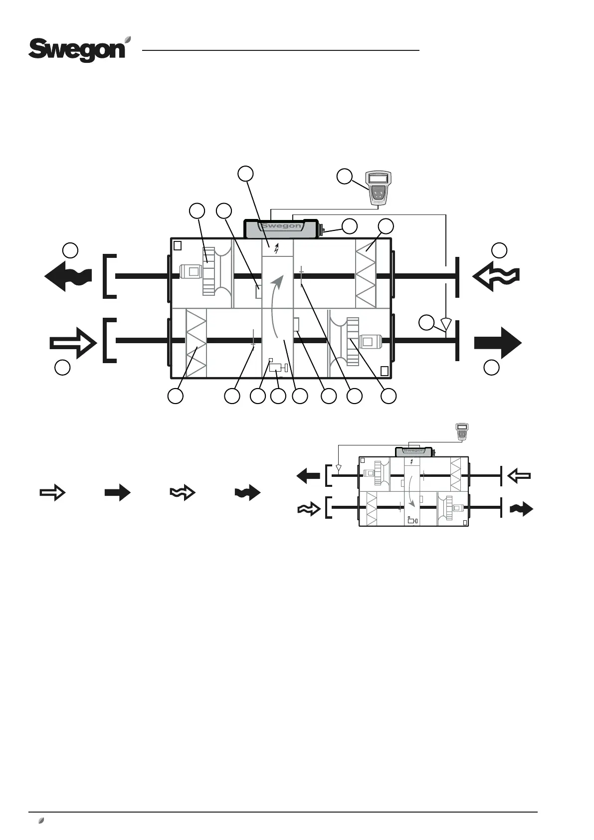
1.5 The Components of the Air Handling Units
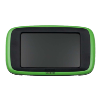
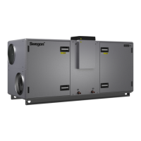
1.5.1 COMPACT Unit
The individual components each specified below in a simplified and
diagrammatical description.
The air handling units are supplied in the right-hand ver-
sion as shown in Fig. 1a.
Coversion to the left-hand version as shown in Fig. can be
carried out via a simple adjustment in the control equip-
ment. See 3.4.1.2. The air handling unit can be installed
vertically. See 3.4.1.1.
In the left-hand version (Fig. 1b), the components marked
with an asterisk change function and designation (the
components are named according to whether they are for
supply air or extract air).
The arrangement of the components
and their designations
1
OUTDOOR AIR* (Left-hand version: Extract air)
2 EXHAUST AIR* (Left-hand version: Supply air)
3 Extract air fan* with motor and motor control system
4 Pressure sensor, extract air fan*
(Position on function selector switch = 1)
5 Electrical equipm. cubicle with control unit
6 Hand-held micro terminal
7 Main switch/Safety switch
8 Extract air filter*
9 EXTRACT AIR* (Left-hand version: Outdoor air)
10 SUPPLY AIR* (Left-hand version: Exhaust air)
11 Supply air temp. sensor (to be mounted in supply air duct)
12 Supply air fan* with motor and motor control system
13 Extract air temperature sensor*
14 Pressure sensor, supply air fan*
(Position on function selector switch = 2)
15 Heat exchanger
16 Drive motor, heat exchanger
17 Sensor, rotation monitor
18 Outdoor air temperature sensor*
19 Supply air filter*
Left-hand version
Fig 1b
Outdoor air Supply air Extract air Exhaust air
1
2
Fig 1a
1
2
3 4
5
6
11
7 8
10
9
1213141516171819