GB.COMPACTUT.170622
Registered design. The company reserves the right to make design changes without prior notice.
www.swegon.com 9
N L3 L2 L1 PE
N L1 PE
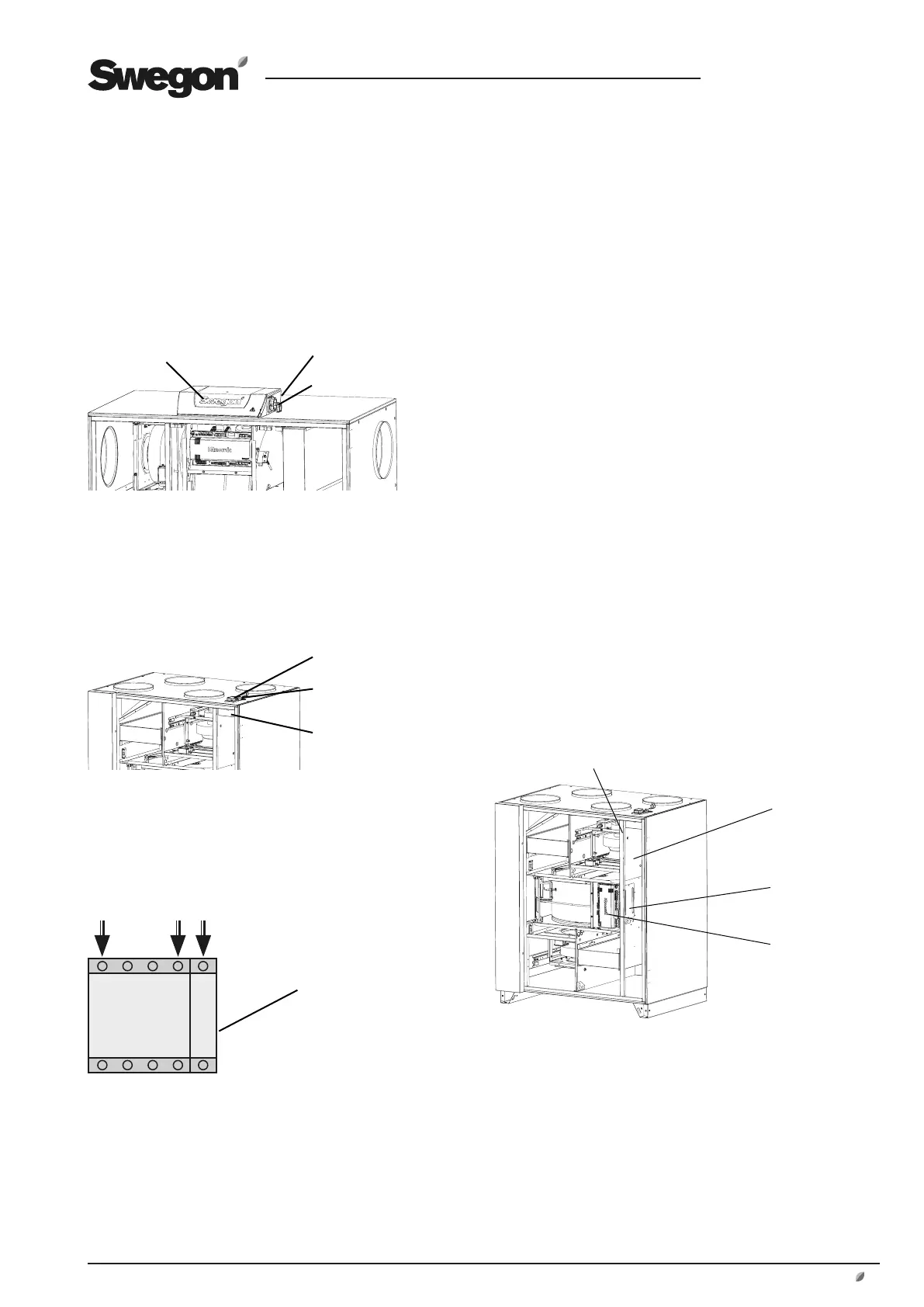
3.7 Connection to the Electric Power Grid
Connection of the power supply cable from the mains
must be wired across a safety isolating switch.
3.7.1 Access
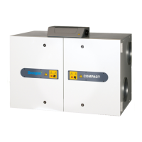
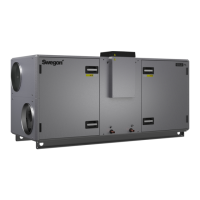
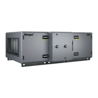
COMPACT Unit
Remove the upper section of the junction hood. Run the
cable through the cable gland on the backside of the junc-
tion hood.
3.8 To Connect External Cables
3.7.1 COMPACT Unit
To gain access to the control unit, remove the cover plate
in front of the heat exchanger. Remove the upper section
of the junction hood. Cables from external sources can
be run in to the electric cubicle through the rubber dia-
phragm on the backside of the junction hood.
N.B.! Cables for external communication outside the air
handling unit must be arranged at a minimum distance of
100 mm from any current-carrying (live) cable.
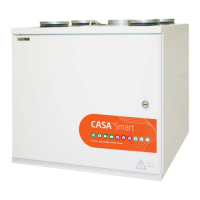
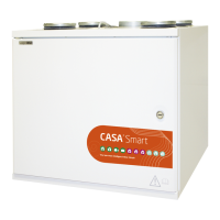
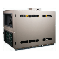
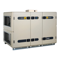
3.7.2 COMPACT Top
To gain access to the power unit, remove the cover plate
in the unit’s extract air duct.
Cables from external sources can be run into the air han-
dling unit through the rubber diaphragm by the extract air
intake, located at the top of the unit.
The external cables can be extended in the existing cable
protection in the extract air duct of the unit. Bundling
straps are pre-fitted inside the cable protection. After
running the cables, secure them by pulling the bundling
straps tight.
Cables can be run in to the electric cubicle according to
appropriate hole indication in the rubber diaphragm.
N.B.! Cables for external communication outside the air
handling unit must be arranged at a minimum distance of
100 mm from any current-carrying (live) cable.
Junction hood
Safety isolating switch
Safety isolating switch
Cover
COMPACT Top
Open the inspection panel and dismantle the cover. Run
the cable through the cable gland by the safety isolating
switch.
Cable gland
Cable gland
3.7.2 Electrical Connections
1-phase, 3-wire, 230 V -10/+15%, 50 Hz, 10 AT.
Safety isolating switch
Electrical equip-
ment cubicle
Extract air duct
of the air han-
dling unit
Cable protection
Cover plate