14
C
Flow
™
Space
Operatin
Manual
March 2021
All installed light sources except 638 nm or 640 nm diode lasers are
switched by hardware switches located at the left side of the flow
cytometer. The laser switches are located above the instruments main
on/off switch. Lasers will be only on power when the main instrument
power is on. Red laser diodes, 638-640 nm are switched by a software
switch in FloMax
®
.
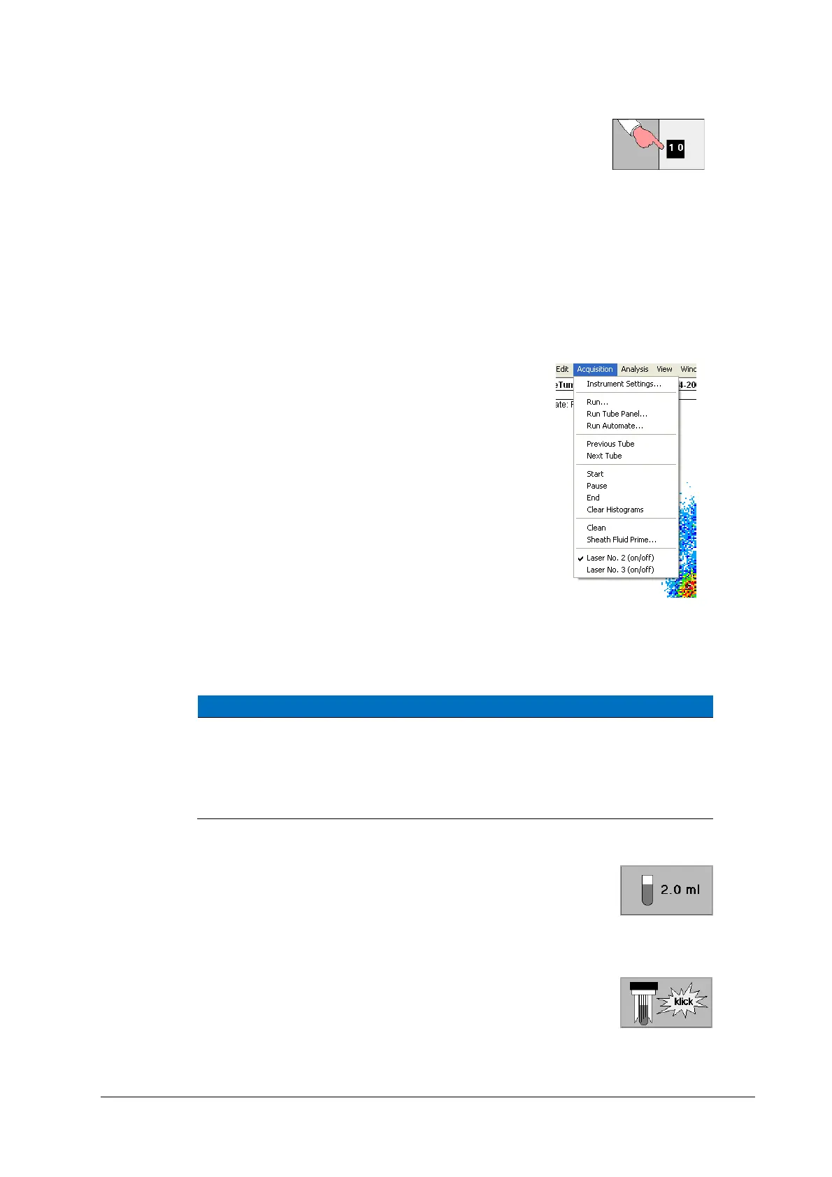
Select “Acquisition” from the upper command line and click on Laser No.
2 to power the laser on. The tick indicates that the laser is switched on.
The software switch Laser No. 3 has no function in CyFlow™ Space
systems.
Laser operation status is saved in Instrument settings files.
In the standard configuration all particles pass through laser
spot no. 1 of the 488nm laser – the leading laser – first and
then through the laser(s) at spot no. 2 and no. 3 (if present).
Therefore, all parameters derived from a laser located at a spot
other than no. 1 require a time delay. Time delay of detectors
is set in the Parameter Setup dialog box (see chapter 9.1).
5.3 Starting a Measurement
NOTICE
Please see “FloMax
®
- Acquisition and Instrument control” on how to
change instrument settings.
Make sure your flow cytometer is ready for analysis and the operating
software is prepared for the measurement.
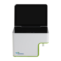
1. Prepare sample according to the Application Notes and
preparation procedures, resp. Use not less than 830 µl for true
volumetric absolute counting and not more than 2.8 ml. For smaller
amounts of sample use Small Volume Sample Tubes (REF 04-2010, however these
tubes are not compatible with the True Volumetric Absolute Counting option).
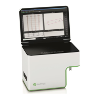
2. Insert sample tube into the sample port until you recognize a
"click". The sample should be fully mounted within a second.