Do you have a question about the SYSMEX SF-3000 and is the answer not in the manual?
Introduces the SF-3000 analyzer, its capabilities, and the manual's structure.
Explains the manual's chapter organization and content for efficient information retrieval.
Details the use of NOTE, CAUTION, and WARNING boxes and document conventions.
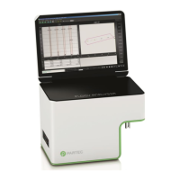
Introduces the SF-3000 analyzer's main elements and options.
Lists optional features to enhance system efficiency like bar code readers and printers.
Covers crucial safety considerations for operating, maintaining, and servicing the SF-3000 analyzer.
Summarizes operating procedures for different modes, screen displays, and touch panel functions.
Lists the 23 parameters analyzed by the SF-3000, their acronyms, and detection methods.
Explains the layout and components of the LCD screen, including status and menu areas.
Explains the password system for protecting QC, Settings, and Calibration programs.
Details the procedure for shutting down the analyzer in an emergency situation.
Describes the three types of alarm sounds used to alert the operator.
Outlines necessary space, electrical, and environmental requirements for installation.
Provides detailed technical specifications for the SF-3000 system.
Introduces sample processing modes: manual open, capillary, auto (sampler), manual closed, and manual CP.
Outlines essential operator checks before starting the SF-3000 system, including reagents and equipment.
Explains how to perform QC analysis in Manual Mode, including sample number setting and QC file specification.
Details the operational steps for Manual Open, Capillary, Auto, Manual Closed, and Manual CP modes.
Details the shutdown sequence for cleaning detector chambers and manometers.
Explains the timer mode for automatically switching off the pneumatic unit power after inactivity.
Introduces the Work List function for specifying samples and processing analysis information.
Details how to input analysis information using the Work List display and its second menu.
Details how to download order information from a host computer or floppy disk.
Explains how to delete specified order information from memory, including current, marked, or all data.
Describes how to print the list of order information to a Graphic Printer.
Explains how to copy registered order information to a floppy disk for backup purposes.
Introduces the chapter on analysis results, screen displays, output, and processing.
Explains the system's IP messages, their meanings, and conditions for appearance.
Explains how stored analysis data is displayed in list format and how to select data types.
Describes how to display scattergrams and particle size distributions for analyzed data.
Outlines the process for reviewing and validating data for report output.
Explains how to mark data in the List Display with a yellow square for output or deletion.
Allows the operator to select the type of samples to be displayed in the List Display.
Allows specifying data to display at the top or bottom of the List Display.
Arranges List Display data chronologically or by Sample ID order.
Allows changing sample information of stored analysis data.
Explains how to output specified stored data to printers or host computer.
Explains how to delete specified stored data from the List Display.
Explains how SF-3000 automatically prints or transmits analysis data based on preset conditions.
Emphasizes periodic maintenance for keeping the SF-3000 in optimal operating condition.
Provides a periodical maintenance checklist for daily, weekly, monthly, yearly, and as-needed tasks.
Details daily maintenance procedures, including cleaning detector chambers and removing fluid from the pneumatic unit trap chamber.
Outlines weekly maintenance tasks, including cleaning the SRV tray and executing the WBC detector cleaning sequence.
Covers monthly maintenance tasks like cleaning the orifice, waste chamber, and sample rotor valve.
Describes the annual visual inspection for laser safety.
Details maintenance procedures required based on specific conditions or errors, such as cleaning mechanisms or removing clogs.
Lists procedures for replacing consumables like reagents, piercers, fuses, and belts.
Explains how to reset system unit operation counters after maintenance.
Provides instructions for formatting a 3.5-inch floppy disk for SF-3000 use.
Lists all supplies and replacement parts with their part numbers and reference sections.
Explains the purpose of Quality Control (QC) in checking analysis data accuracy and precision.
Describes how to delete existing QC data from memory for new lots or level changes.
Covers setting the control method (X or L-J) and limit display method for QC.
Allows excluding unnecessary parameters from X/L-J and X M QC analysis.
Explains how to start/stop X M Control and set the number of samples per batch.
Used for manually setting or downloading QC target and limit values.
Displays QC charts for data output, statistical calculations, and data point deletion.
Details how to perform QC analysis in Manual, Closed, or Manual CP modes using control blood.
Explains how L-J Control can be performed in Auto Mode using control blood.
Covers commercial control applications (X, L-J) and patient sample analysis (X M).
Calculates control target values automatically from stored data.
Defines how QC charts are read using the Levy-Jennings Method and how abnormalities are displayed.
Explains calibration purpose for compensating system biases to maintain accuracy.
Details the automatic calibration procedure for HGB and HCT using reference samples.
Explains how to calibrate HGB and HCT values manually by entering updated values.
Guides on accessing, deleting, and outputting calibration histories.
Introduces the chapter on error messages, countermeasures, maintenance, status displays, and error logs.
Provides an alphabetical index of error messages and a troubleshooting guide for problems encountered.
Details test programs for checking system operation and identifying causes of abnormalities.
Explains how to check the system status, including analyzer condition, process status, and sensor status.
Describes how to display past errors and recovery messages for corrective actions.
Explains that certain components of the SF-3000 system may require adjustment.
Details how to check and adjust pneumatic unit and main unit pressures and vacuum levels.
Provides procedures for adjusting pneumatic unit pressure and vacuum levels.
Covers adjusting main unit pressure and vacuum to specific levels.
Explains how to adjust the contrast of the LCD screen using the control knob.
Provides instructions for adjusting the ID Bar Code Reader, including installation and testing.
Explains detection principles, analysis methodology, procedures, and hardware components of the SF-3000.
Describes flow cytometry by semiconductor laser and DC detection methods for blood cell analysis.
Illustrates the sample flow for WBC and RBC/PLT/HGB analyses.
Explains the analysis flow for Red Blood Cells, Platelets, and Hemoglobin.
Details the classification of white blood cells using flow cytometry.
Explains how scattergrams show 2D distributions of cell size and intracellular density.
Covers analysis of RBC and PLT particle size distribution, including RDW and PDW.
Describes the electronic system of the Main Unit and its microprocessor control.
Identifies and describes components on the Main Unit's front, rear, sides, and interior.
Identifies and describes components of the Pneumatic Unit, including gauges, regulators, and switches.
Details the components and functions of the optional Cap Piercing Sampler Unit.
Describes the components and function of the optional Manual CP Unit.
Explains the reagent system, including Diluent, Lyse Reagents, and Detergent.
Explains that system setup is performed by the Sysmex Service Representative but can be modified by the user.
Covers setting conditions for Auto Output, Auto Erase, and Auto Validation for peripheral devices.
Allows setting criteria for marking abnormal data (Mark Limits, Critical Limits) and stopping auto mode analysis (Stop Limits, Stop Conditions).
Enables setting limits for Abnormal IP Messages for WBC, RBC, and PLT.
Sets printer output conditions, print formats, and Host Computer interface parameters.
Allows setting system status such as Date/Time, Units, Password, Timer Mode, Normal Range, etc.
Programs to print settings to a Graphic Printer and copy setting data to a floppy disk.
Shows the top-level menu structure of the SF-3000 system.
Lists the main menu options accessible from the Sysmex key.
Lists the menu options related to the Sampler unit.
Covers verifying box contents, power, and environmental considerations before installation.
Specifies the recommended space around the instrument for servicing and heat dissipation.
Details procedures for removing packing material from the front cover, front panel, and main unit chassis.
Instructions for installing the supplied tray.
Guides on attaching the ID Unit to the Main Unit chassis and connecting its wire cord.
Details the installation of the CP Sampler Unit, including removing covers, mounting metals, and connecting tubes.
Covers the installation of the Manual CP Unit, including attaching dummy covers and grounding wires.
Explains how to connect pneumatic unit vacuum and pressure lines, and reagent lines.
Describes the procedure for installing the battery backup PCB.
Details connecting host computer, printers, and pneumatic unit power.
Outlines procedures for initial power-on and system setup, including system checks.
Details the serial interface specifications for connecting to a host computer, including connection and pin assignments.
Describes the formats for patient sample data, QC data, and inquiry data transmission.
Covers applicable bar codes, their elements, wide/narrow ratio, optical requirements, and check-digit methods.
| Brand | SYSMEX |
|---|---|
| Model | SF-3000 |
| Category | Measuring Instruments |
| Language | English |