FUNCTIONAL DESCRIPTIONS, Pneumatic Unit
Sysmex SF-3000 Operator's Manual -- Revised September 1995 10-33
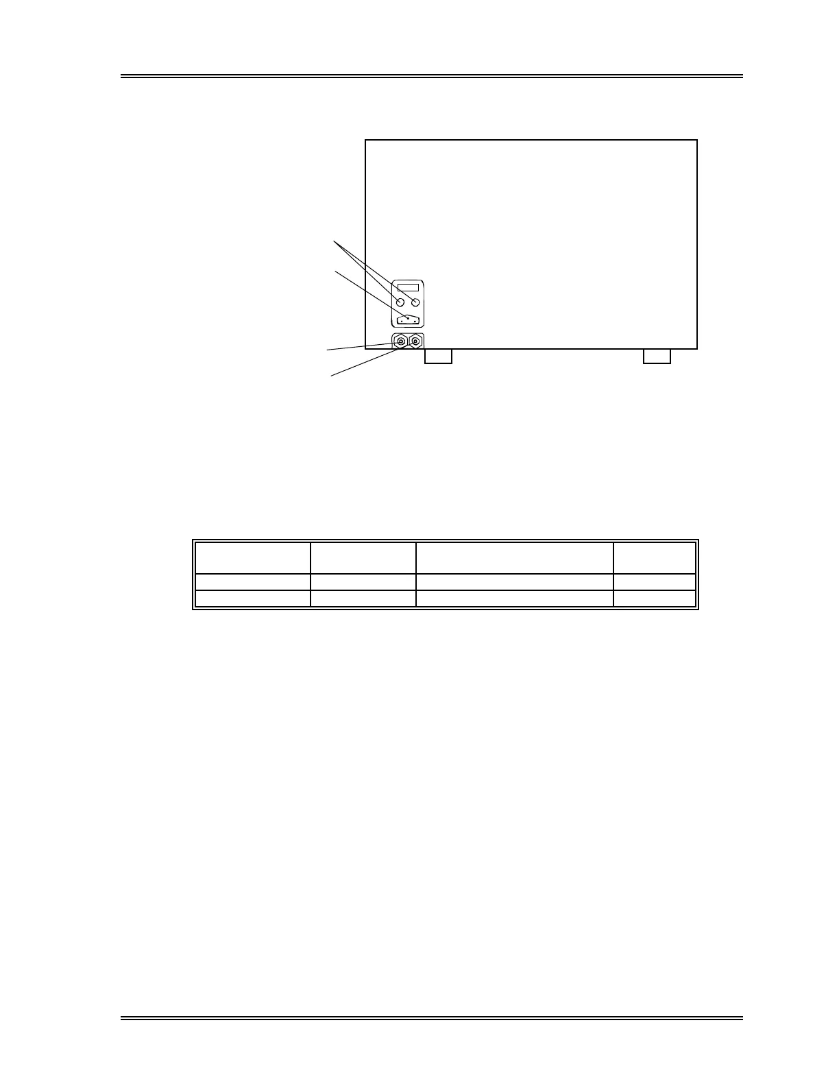
10.2 Right Side
(1) Fuse
(2) Power Connector
(3) Vacuum Outlet
Nipple
(4) Pressure Outlet
Nipple
Figure 10-26: Pneumatic Unit – Right Side View
(1) Fuse
Replace with provided time lag type fuse. The rating will be different depending
on the instrument specification.
Specification Part No. Description Fuse
Type
117 VAC 266-5011-3 Fuse 250V4A ST4-4A-N1 Time Lag
220/240 VAC 266-5292-6 Fuse 250V2A No. 19195 Time Lag
(2) Power Connector
Connects with the Pneumatic Power Outlet on the Main Unit right side panel.
(3) Vacuum Outlet Nipple
Vacuum is supplied to the Main Unit through this nipple. Connects with the
vacuum inlet nipple on the Main Unit.
(4) Pressure Outlet Nipple
Pressure is supplied to the Main Unit through this nipple. Connects with the
pressure inlet nipple on the air drier on the rear panel of the Main Unit.