TECHNICAL INFORMATION
C-2 Sysmex SF-3000 Operator's Manual -- Revised September 1995
1. SERIAL INTERFACE FOR HOST COMPUTER
A serial interface is available on the Main Unit rear panel for connecting to a host
computer. The bit serial voltage type, which conforms to the RS-232C interface, is used
for input and output to and from the SF-3000.
1.1 Connection
Connect an EIA RS-232C V.24 standard 9-pin D-SUB, female (body = female and pins
= male) connector (DB-9S) to the serial interface on the Main Unit rear panel. Fixing
screws for this connector have an inch thread.
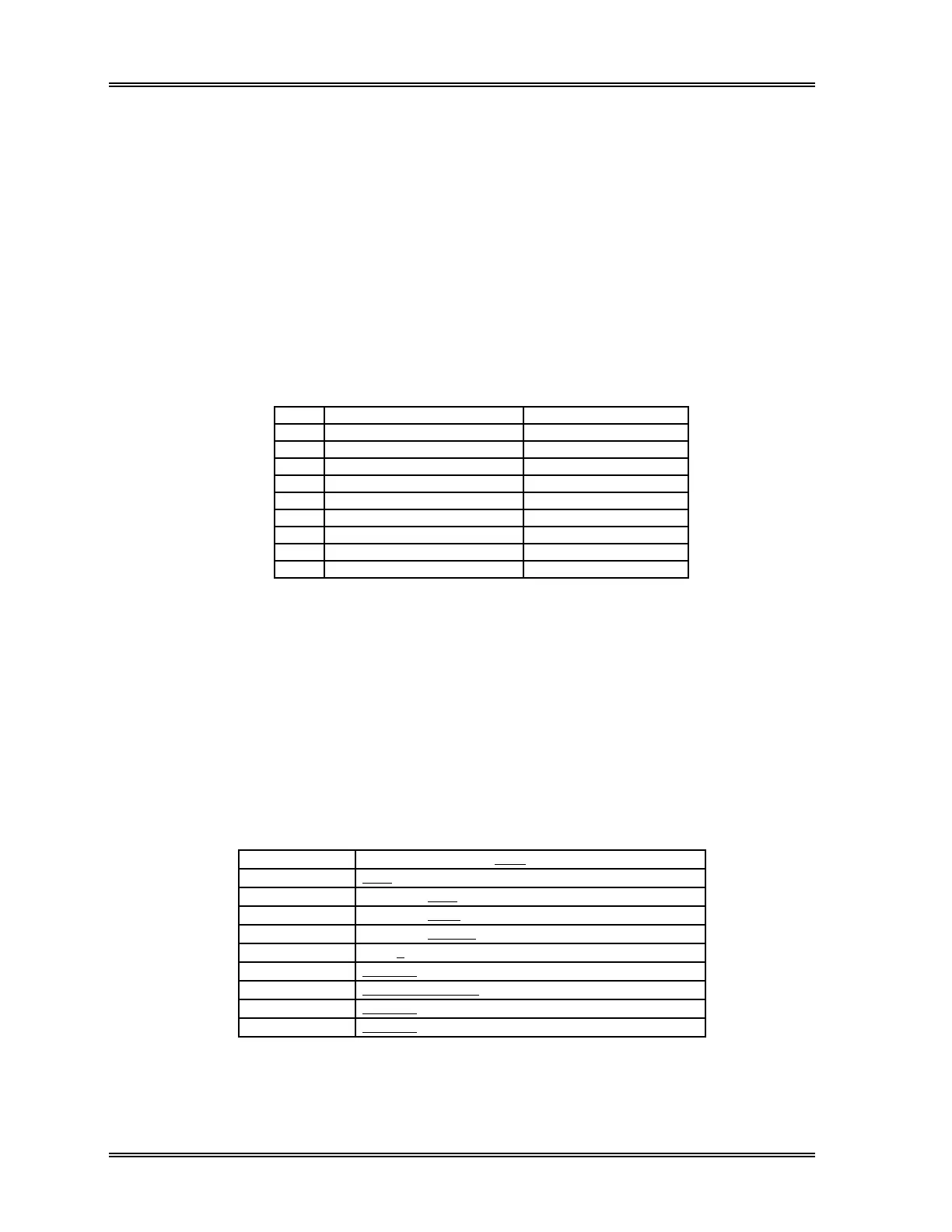
1.2 Input/Output Signals
PIN SIGNAL NAME FLOW DIRECTION
1
2 Receive Data (RxD) IN (From Host to SF)
3 Transmit Data (TxD) OUT (To Host from SF)
4 Data Terminal Ready (DTR) OUT (To Host from SF)
5 Signal Ground (SG)
6 Data Set Ready (DSR) IN (From Host to SF)
7 Request to Send (RTS) OUT (To Host from SF)
8 Clear to Send (CTS) IN (From Host to SF)
9
Table C-1: RS-232C Pin Assignment
1.3 Communication Format
Asynchronous Half Duplex Mode
1.4 Baud Rate/Character Structure
Setting program "Settings" - "Output Condition" - "HC Setting" has to be executed to set
the interface parameters. Underlined items are selected as a default configuration.
Baud Rate 600 1200 2400 4800 9600
Code 7-Bit 8-Bit
Stop Bit 1-Bit 2-Bit
Parity Bit None Even Odd
Class Class A Class B
Interval 0 23571015
Sampler No. 12 Digits 13 Digits
RDW Output RDW-SD+RDW-CV RDW-SD RDW-CV
PDW Output Transmit Not Transmit
P-LCR Output Transmit Not Transmit
Table C-2: Host Computer Settings