FUNCTIONAL DESCRIPTIONS, Main Unit
10-20 Sysmex SF-3000 Operator's Manual -- Revised September 1995
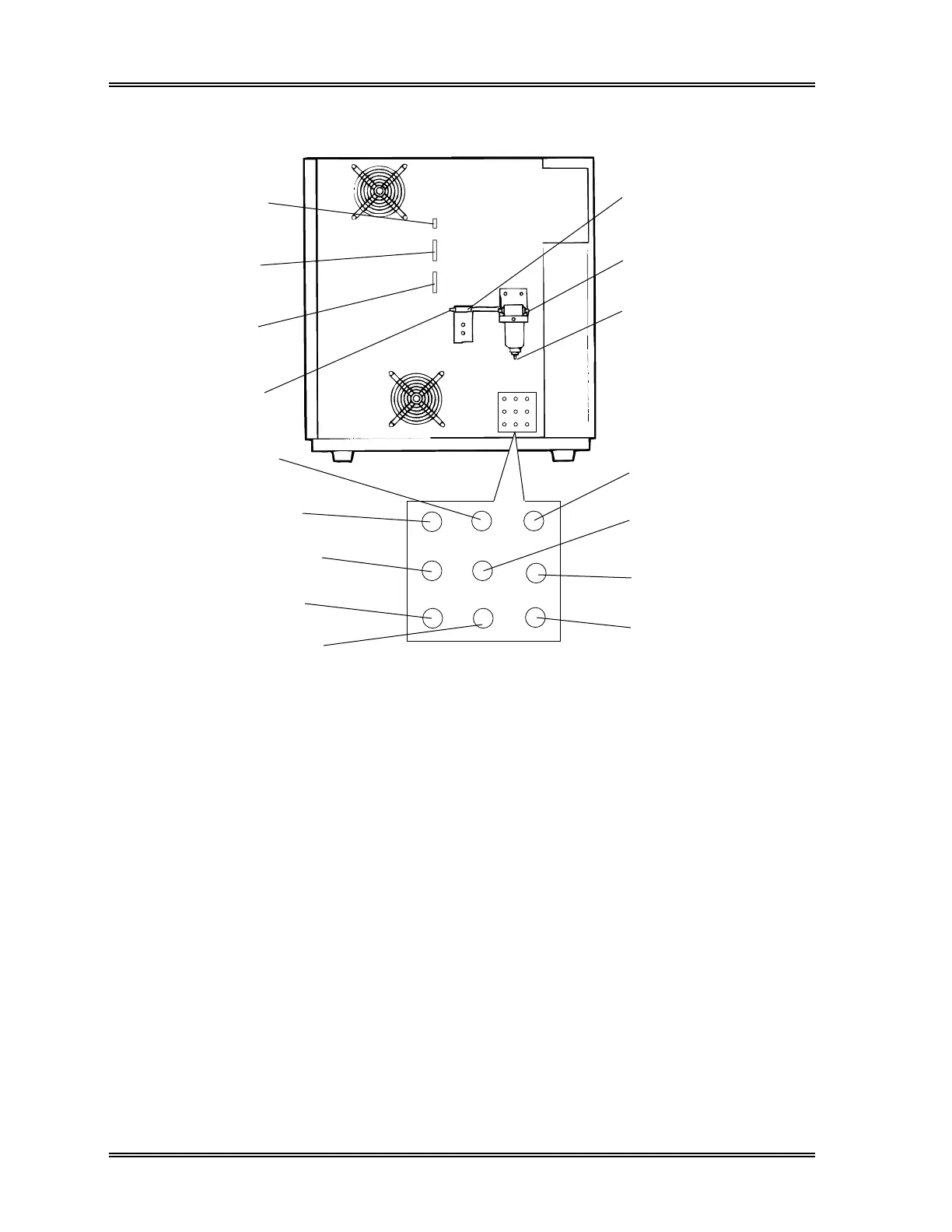
9.2 Rear
(8) Drain Inlet Nipple
(11) PK Inlet Nipple (PK)
(12) SLS Inlet Nipple (SLS)
(1) Host Connector
(2) GP Connector
(3) DP Connector
(4) Air Drier Outlet
Nipple
(9) Pressure Inlet Nipple
(10) FBA Inlet Nipple (FBA)
(5) Air Drier
(6) Air Drier Inlet Nipple
(7) Air Drier Drain
Outlet Nipple
(13) Vacuum Inlet Nipple
(14) FDO Inlet Nipple (FDO)
(15) FDT Inlet Nipple (FDT)
(16) Waste Outlet Nipple
Figure 10-18: Main Unit – Rear View
(1) Host Connector
Used for communication with the host computer.
(2) GP Connector
Used as the output connector for the graphic printer.
(3) DP Connector
Used as the output connector for the data printer.
(4) Air Drier Outlet Nipple
Connects to the pressure nipple on the Main Unit.
(5) Air Drier
Removes dust and moisture from the (pressure side) air supplied by the
Pneumatic Unit.
(6) Air Drier Inlet Nipple
Connects to the pressure nipple on the Pneumatic Unit.