INSTALLATION
B-22 Sysmex SF-3000 Operator's Manual -- Revised September 1995
8. TUBE CONNECTION
8.1 Vacuum Line
Connect the Pneumatic Unit, vacuum outlet nipple (marked VACUUM and a blue label)
and Main Unit vacuum inlet nipple (marked VACUUM) using the polyurethane tube (4
mmID x 6 mmOD) provided.
8.2 Pressure Line
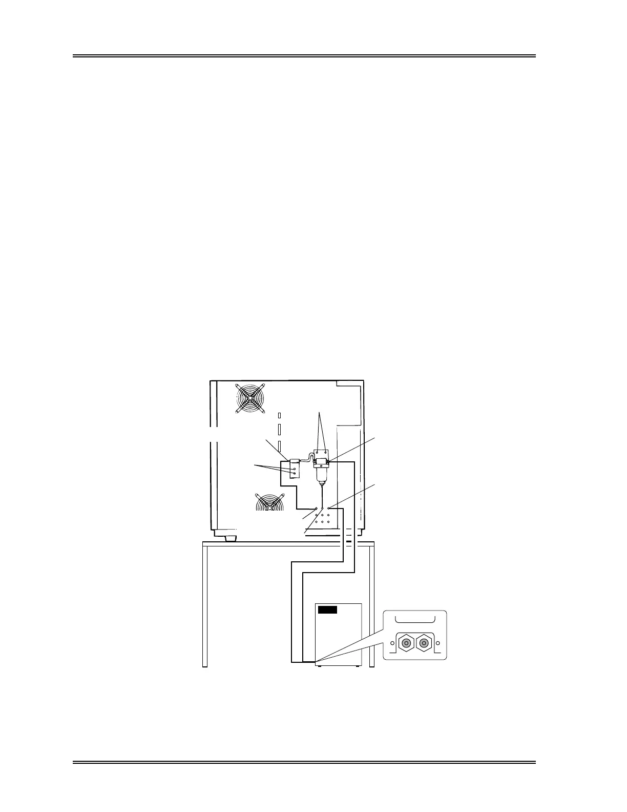
(1) Install the air drier to the rear panel (see Figure B-31). Fit the air drier, and secure
it using the provided binding screws M4 and flat washers M4.
(2) Connect the Pneumatic Unit pressure outlet nipple (marked PRESSURE and a red
label) to the air drier inlet nipple using the provided polyurethane tube (4 mmID x
6 mmOD).
(3) Connect the instrument pressure inlet nipple (marked PRESSURE) to the air drier
outlet nipple using the provided polyurethane tube (4 mmID x 6 mmOD).
(4) Connect the air drier drain outlet nipple at the bottom of air drier to the drain inlet
nipple using the provided polyurethane tube (1.8 mmID x 3.4 mmOD).
Pneumatic Unit
PRESSURE
VACUUM
Air Drier Inlet Nipple
Vacuum Inlet Nipple
Drain Inlet Nipple
Pressure Inlet Nipple
Air Drier Outlet Nipple
Screw Bindings
M4 x 20
Screw Bindings M4 x 6
Washer Flat M4
Figure B-31: Pneumatic Tube Connections