V/D
S
ERIES
E
LECTRICAL ASSEMBLIES
Revision: 2.1 4-7
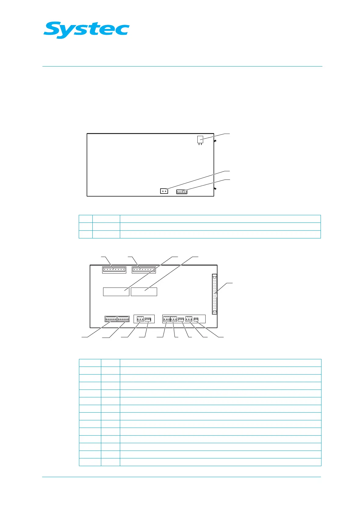
4.1.3 Analogue circuit board AS1002
The analogue circuit board AS1002 connects all analogue and digital
inputs and all outputs to the digital circuit board DS1002 via the 40-pin
ribbon cable. The gain and offset values from the calibration process are
stored here.
Fig. 5: Top of the analogue circuit board AS1002
1 JP12 5 V DC for analogue inputs
2 JP13 24 V AC for digital outputs
3 JP15 5 V DC for digital outputs
Fig. 6: Underside of the analogue circuit board AS1002
1 JP14
Electrodes (E1 – E3)
2 JP6 Drain temperature sensor (TS4, drain temp)
3 JP4 Pressure transducer on steam generator (PS1, gen press)
4 JP5 Temperature sensor 2 on sterilisation chamber (TS3, chamber temp 2)
5 JP3 Flow sensor (TS2, condense temp)
6 JP1 Pressure transducer on sterilisation chamber (PS2, chamber press)
7 JP2 Temperature sensor 1 on sterilisation chamber (TS1, chamber temp)
8 JP11
Digital inputs
9 JP10
Digital inputs
10 JP9 Digital outputs
11 JP7 Digital outputs
12 JP16
Test points
13 JP17
Test points
14 JP8 Connection for 40-pin ribbon cable to digital circuit board DS1002
 Loading...
