V/D
S
ERIES
E
LECTRICAL ASSEMBLIES
4-12 Revision: 2.1
4.1.7 230 V circuit board ACT1
The ACT-1 circuit board contains the input filters for the mains voltage on
the power supply and the 230 V AC outputs (e.g. for the pumps).
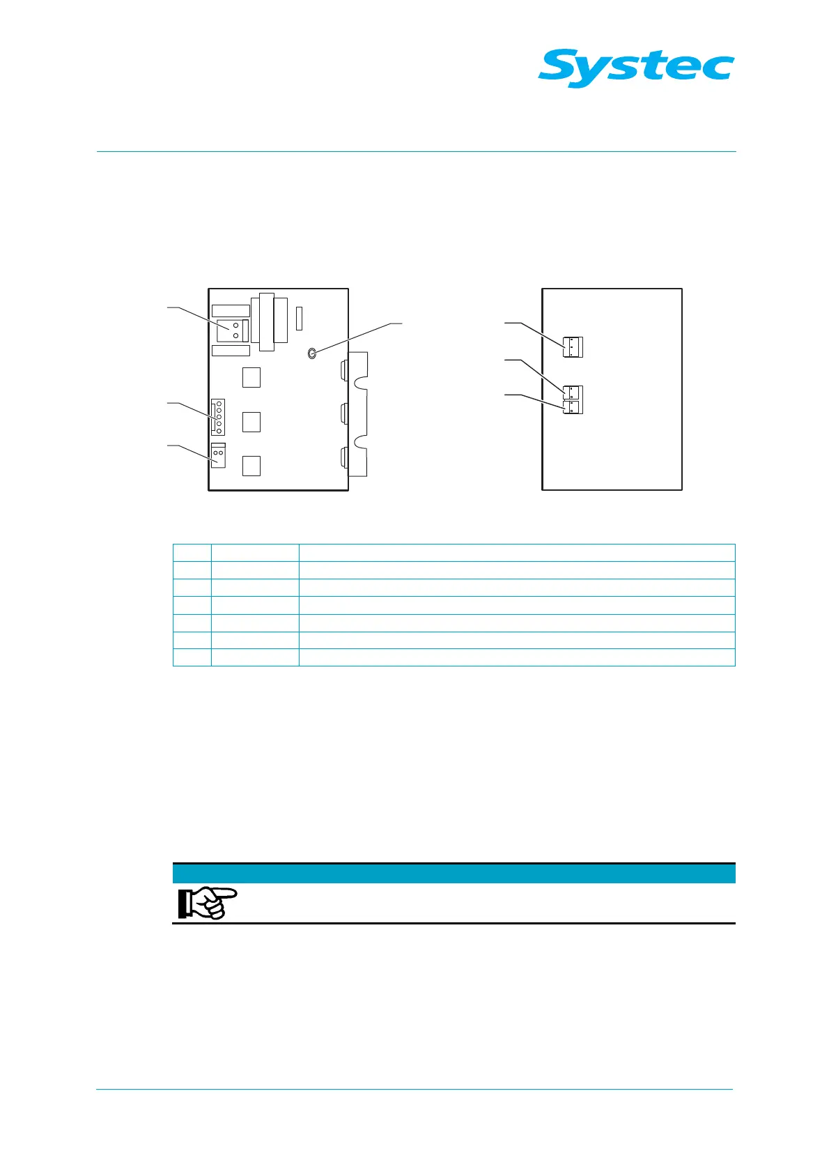
Fig. 11: ACT1 circuit board, top and underside
1 JP2 Output (230 V) for power supply
2 JP1 Connection for digital outputs on AS1002
3 JP5 Output for heater solid state relay (5 V DC)
4 SSR-IN Power supply for toroidal transformer
5 JP3 AC_T1, 230 V AC input
6 JP4 AC_T1, 230 V output for vacuum pump (M2)
7 JP7 AC_T1, 230 V output for water feed pump
The circuit board also has three switched 230 V outputs (via optocoupler,
TRIACs – see Fig. 4: oben pos. 7, 8, 9) for the following:
− Vacuum pump (JP4)
− Water feed pump (JP7/1)
− Air compressor (JP7/2)
The following are also switched via output JP7/2, when necessary:
− Heater contactor
− Y13 valve
Special features on V-40/55 and D-45
On the V-40/55 and D-45, the air compressor is switched
directly via the mains switch.
 Loading...
