V/D
S
ERIES
M
ECHANICAL ASSEMBLIES
3-12 Revision: 2.1
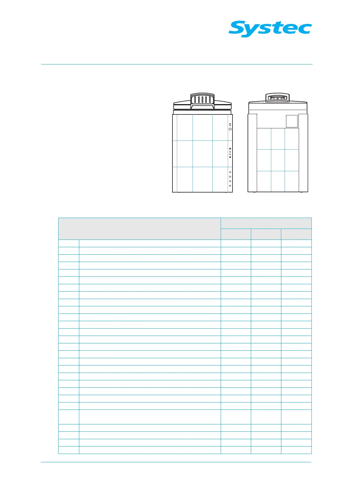
3.2.2 V-65 – 150
21 2322
24 2625
27 2928
11 1312
14 1615
17 1918
Fig. 2: V-65 – 150: Layout diagram of rear and front
Component
Position in layout diagram
VX VE VB
Steam generator 17/18
Pneumatic assembly 13 13 13
BV1 Manual drain tap for steam generator 18
D1 Steam air extractor for sterilisation chamber 27 27 27
D2 Steam air extractor (Super Dry) 19
E1 High electrode 15
E2 Low electrode 15
F1 Demineralised water flow monitor 15
F2 Vacuum flow monitor 19 19
M1 Demineralised water feed pump 15 18 (opt.)
M2 Vacuum pump 19 19 19
M3 Air compressor 14 18 18
N1 Needle valve for air extraction 27 27 27
NR6 Needle no-return valve – “Blow out cooling coil” 13 13
NR7 Needle no-return valve for cavitation protection 19 19
P1 Manometer for external compressed air 19 19
P2 Manometer for internal compressed air 17 17 17
PR1 Pressure reducer for external compressed air 19 19
PR2 Pressure reducer for cooling water 19 19
PS1 Pressure transducer for steam generator 12
PV1 Compressed air reservoir 17 17 17
PV2 Exhaust filter 24 24
R1 No-return valve for demineralised water 18 17
R2 No-return valve on pressure transducer for steam
generator
12
R3 No-return valve for cooling water 19 19
R4 No-return valve for compressed air inlet 11 21 21
R5 No-return valve for drain 28 28 28
R6 No-return valve for air compressor 17 17 17