54 PDRP-2001 Series Manual — P/N 53043:E4 7/28/2016
Programming Master Programming Level
Output Circuit #2 default programmed as Waterflow NAC will not activate (No)
Output Circuit #3 default programmed as Release 1 will activate (Yes)
Output Circuit #4 default programmed as Supv Bell NAC is not mapped (N/A)
Note that the MAP may indicate that an Input Zone is programmed to a particular Output Circuit
but, if it is cross-zoned with one or more other Input Zones, all must be active in order to activate
the Output Circuit. Refer to the examples in “Circuit Mapping and Cross-Zoning” on page 91.
The Output Circuit Map can be customized by selecting or deselecting any of the four output
circuits for activation. Pressing the number key corresponding to the selected output will toggle the
display between Yes for activation by the Input Zone to No for no activation. The new customized
programming is automatically saved by the panel as soon as it is entered.
Freeze Supervision
Pressing 2 for Freeze Supervision while viewing Edit Input Zone Screen #3, will program the
FACP to supervise the devices connected to the selected zone for a temperature freeze condition.
Each press of the 2 key will toggle the display between Freeze Supv. Yes and No. The factory
default setting is No Freeze Supervision.
Adjective/Noun
The Adjective/Noun selection allows the programmer to enter specific descriptors about the
detector currently being programmed. Pressing 1 while viewing Edit Input Zone Screen #3 will
cause the following screen to be displayed:
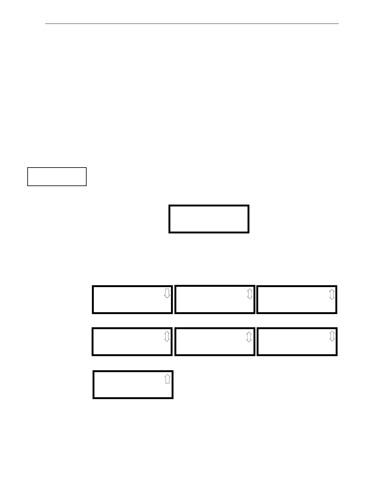
Pressing 1 while viewing the Adjective/Noun Screen will cause the following screen(s) to be
displayed. Note that the keyboard down arrow key must be pressed to see all the Adjective screens.
Press the number corresponding to the adjective that is to be used as a descriptor for the location of
the detector currently being programmed. When an adjective has been selected, it will appear at the
top of the display as indicated by the asterisks.
INPUT ZONE #
1=ADJECTIVE/NOUN
2=DESCRIPTION
✱✱✱✱✱✱✱✱✱✱✱✱✱✱
Edit Input Zone Screen #3
1=STANDARD ADJECTIVE
2=STANDARD NOUN
Adjective/Noun Screen
1=NORTH
2=SOUTH
3=EAST
Adjective Screen #1
1=WEST
2=FRONT
3=CENTER
Adjective Screen #3
1=REAR
2=UPPER
3=LOWER
Adjective Screen #5
1=MAIN
2=FIRST
3=2ND
Adjective Screen #7
1=3RD
2=4TH
3=5TH
Adjective Screen #2
1=FLOOR4
2=FLOOR5
3=ROOM
Adjective Screen #6
1=FLOOR1
2=FLOOR2
3=FLOOR3
Adjective Screen #4