TA I
NSTRUMENTS
TGA 2050 2–13
FUSE
FUSE
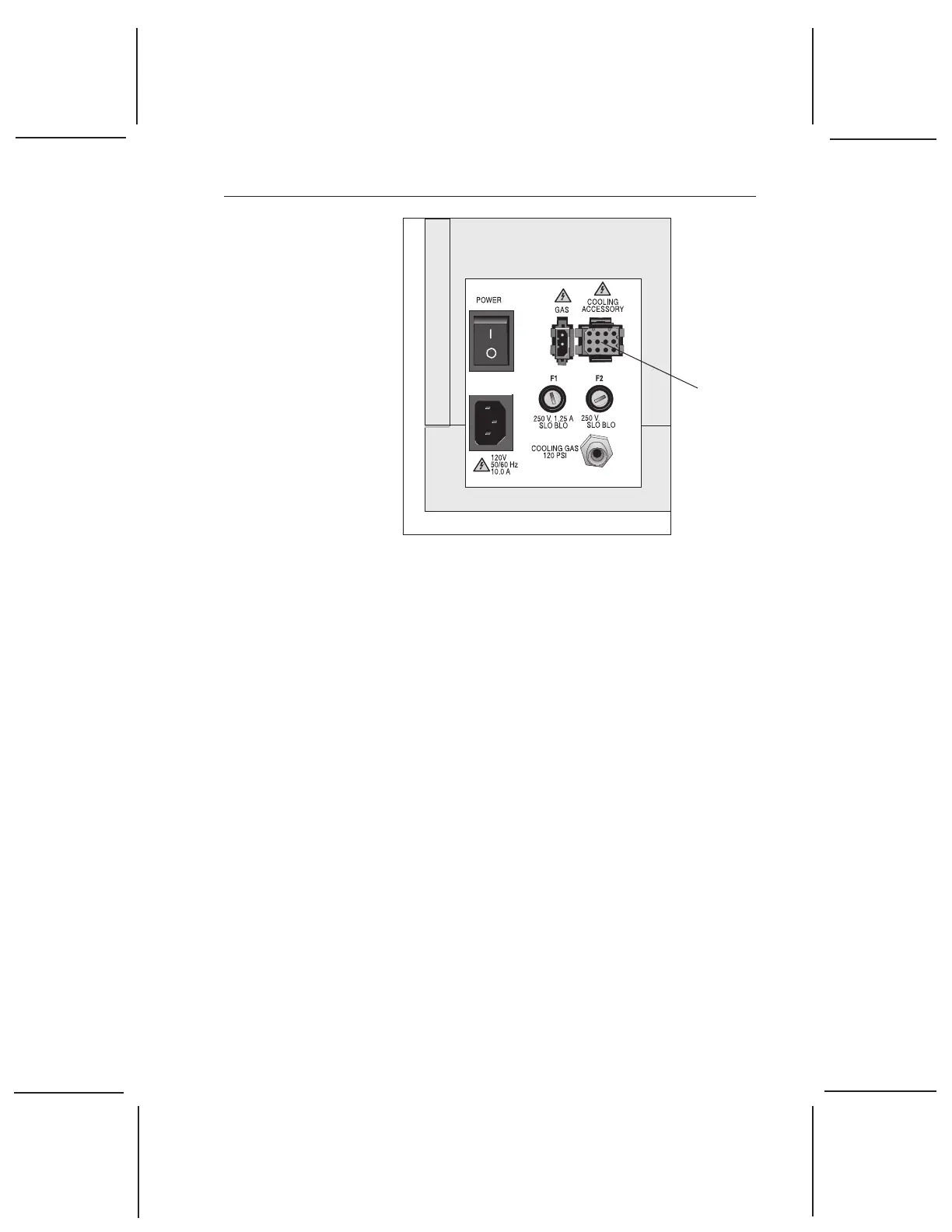
Figure 2.6
TGA Connector Panel
3. Remove the water lines from the packing.
4. Connect one end of the water line marked
“SUPPLY” to the connector labeled “SUP-
PLY” on the left front of the instrument
cabinet.
5. Connect the other end of the water line
marked “SUPPLY” to the connector labeled
“SUPPLY” on the heat exchanger.
6. Connect one end of the unmarked water line
to the connector labeled “RETURN” on the
left front of the instrument cabinet.
7. Connect the other end of the unmarked
water line to the connector labeled “RE-
TURN” on the heat exchanger.
Figure 2.7 on the next page illustrates the
correct water line connections for the TGA
and heat exchanger.
Installing the Instrument
Cooling
Accessory
Connector
10 A
 Loading...