6-4
OPERATING PROCEDURES
Model 336, 338, 339
Operating Procedures
6
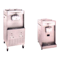
13. Install the adjustable draw handles. Slide the O-ring
into the groove on the pivot pin, and lubricate.
Figure 6-11
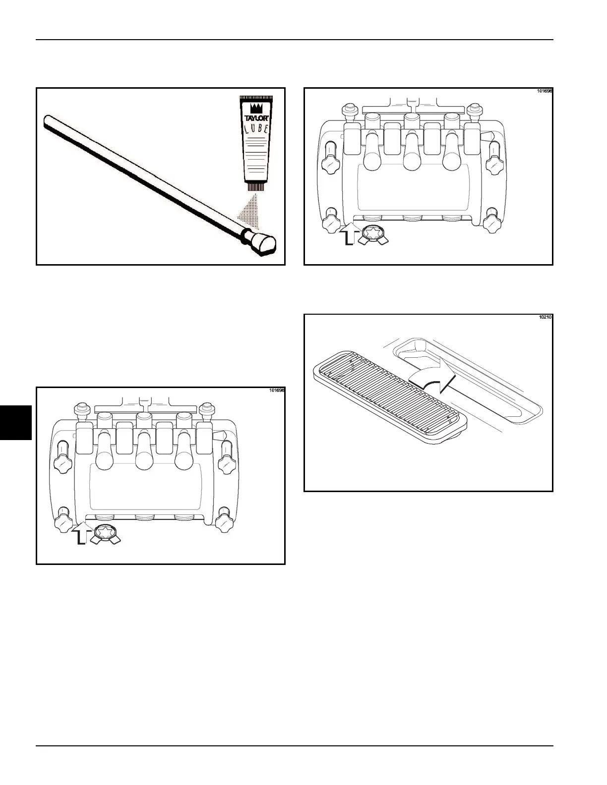
14. Slide the fork over the bar in the slot of the draw
valve. Secure with the pivot pin.
Note: Models 336, 338 and 339 have three draw
handles. Slide the fork of the draw handle in the slot of
the draw valve, starting from the right. Slide the pivot pin
through each draw handle as you insert them into the
draw valves.
Figure 6-12
Note: These units feature adjustable draw handles to
provide the best portion control. The draw handles can
be adjusted for different flow rates. See
"Adjustable Draw
Handle" on page 5-3 for more information on adjusting
these handles.
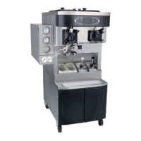
15. Snap the design caps over the end of the door
spouts.
Figure 6-13
16. Install the front drip tray and the splash shield under
the door spouts.
Figure 6-14