OPERATING PROCEDURES
6-3
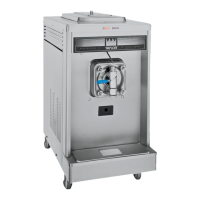
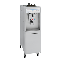
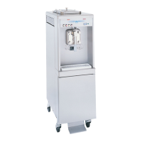
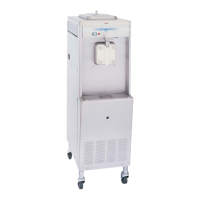
Models 8752 and 8756 with Horizon® Pump
Operating Procedures
6
9. Before assembling the freezer door, check the
following for any nicks, cracks, or signs of wear: door
bearing, door gasket, draw valve, O-rings, and all
sides of the door assembly, including the inside of the
draw valve bore. Replace any damaged parts.
Slide the white plastic front bearing(s) over the baffle
rod(s), making certain that the flanged end of the
bearing is resting against the freezer door. Do not
lubricate the gasket(s) or front bearing(s).
Figure 6-7
Note: There are two gaskets and two front bearings
for the Model 8756 door, one for each freezing
cylinder.
10. Slide the O-rings into the grooves on the prime
plug(s). Apply an even coat of lubricant to the O-rings
and shaft(s).
11. Place the large rubber gasket(s) in the groove(s) on
the back side of the freezer door.
Figure 6-8
Note: There are two prime plugs for the Model 8756
door, one for each freezing cylinder.
12. Insert the prime plug(s) into the hole(s) at the top of
the freezer door(s) and push down.
Figure 6-9
13. Insert the baffle rod(s) through the beater(s) in the
freezing cylinder(s). With the door seated on the
freezer studs, install the handscrews. Tighten equally
in a crisscross pattern to ensure the door is snug.
Note: On Model 8756, the short handscrews go on
the bottom and the long handscrews go on the top.
Figure 6-10
14. Install the draw valve(s). Slide the two O-rings into
the grooves on the draw valve(s).
Model 8756 Only: Slide the O-ring and the H-ring
into the grooves on the center draw valve.
11067
Apply the appropriate
Taylor approved food safe lubricant.
 Loading...