Unpacking
• Open the box. Be careful not to damage the items
within the box with sharp objects, such as knives or
scissors.
• Make sure that the package contains the following
items:
– G-System
– Users Manual
– Power cord
– CAT5 cable
– 4 x 50cm power cables for pedals
– Labels for switches
– Product registration card.
Register you G-System either by sending in the
registration card or via www.tcelectronic.com.
Rackmount or Floormount?
Right out of the box, the entire G-System is assembled
as one floormount unit. But check this out …
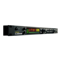
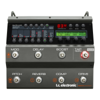
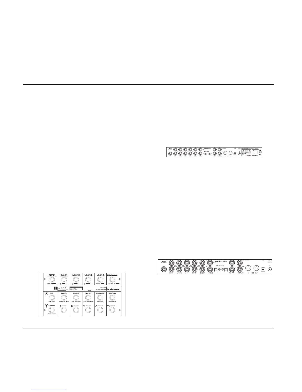
The G-System consists of two main parts.
1) The Control Board – this is the board itself with the
1/4" stereo jack connectors for expression pedals and
the RJ45 connector for the GFX01.
2) The GFX01 – this is the 19" rack unit that contains
the signal processing unit, connectors for loops, the
power supply etc.
Per default, the two units are assembled as an “all-in-
one” floor processor. However, if you wish to have all
loop connectors to your pedals and e.g. a pre-amp neatly
packed away in a 19" rack instead of spreading them all
over the floor, you can easily detach the Control Board
from the GFX01 and mount the GFX01 in your rack. For
more details on the this procedure, please refer to the
“Connections – Rackmount” section on the following
pages.
Connections – Floormount
Now let us connect your G-System. We assume that you
are using the G-System as one floormount unit – as it
was assembled in the factory.
Let’s take a look at the rear panel of the GFX01.
Input Instrument
• Connect your guitar to the socket labeled “Input
Instrument”.
This Quick Setup Guide will help you get started if you already have a basic idea of how you would like to use the G-
System. If you are new to the world of multi-effect processors, you may feel that you need some more “in-depth”
information. In that case, please refer to the relevant chapters of this manual. You may find the “Overview” section (pages
14 to 21) showing connectors, switches and encoders especially useful.
QUICK SETUP GUIDE
8