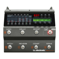
Drive Pedals
TAP TEMPO
EDIT PARAMETER B EDIT PARAMETERC SELECT PAGE
EDIT PARAMETER A
GAIN ADJUST
HOLD TO STORE HOLDTO STORE HOLD TO STORE HOLD TO STOREHOLD TO STORE
PRESETABLE BOOST LEVEL
LEVEL SET
EDITA EDIT B EDIT C
GLOBALTEMPO
FORMANT | WAH | EFFECT FILTERS COMPRESSOR ALGORITHM
MODEMENU
WHAMMY | PITCH ALGORITHMCHORUS | FLANGER | TREMOLO
| RETURNENTER
HI-CLASS | TAPE ECHO | DYNAMIC REVERB ALGORITHM
INPUT DAMP
EDITED
COM FLT PIT DLY REV
E1: E2: E3: E4: E5:
INTEGRATEDEFFECTS
+MANAGEMENT
FILTER LOOP LOOP LOOP EDIT123COMP
UP
DOWN
MOD PITCH DELAY REVERB BOOST
ENCODER ENCODER ENCODER ENCODER ENCODER ENCODER
Expression Pedal
Expression/Volume Pedal
CSA FILE
#108093
S/PDIFUSB
POWER OUTPUTS
PEDAL IN
MIDI
SW OUT
OUTPUTINSERT
LOOP 4LOOP 3LOOP 2
LOOP 1
INPUT
INSTRUMENT
OUTPUT
DO
UL6500
EN/IEC 60065
PROFESSIONAL
AUDIO EQUIPMENT
WARNING
TOREDUCE THE RISK OF FIRE OR ELECTRIC
SHOCKDO NOT EXPOSE THISEQUIPMENTTO
RAINOR MOISTURE
AVIS:
RISQUEDE CHOC ELECTRIQUE-NE PAS
OUVRIR.
100-240VAC 50-60Hz,15W
GF001 | MADE INTHAILAND
QUAD 9V DC OUTPUTS
4x50mA or 200mA totally
CAUTION
R
CUS
THISCLASS B DIGITAL DEVICE MEETS ALL REQUIREMENTS OF THE CANADIAN INTERFERENCE-
CAUSINGEQUIPMENT REGULATIONS AND COMPLIES WITH PART 15 OF THE FCC RULES.
OPERATIONSUBJECT TO CONDITIONS STATEDIN THE MANUAL.
RISKOF ELECTRIC SHOCK
DONOT OPEN
RETURNRETURN RETURN RETURN
SENDSEND SEND SEND
L
(mono)
1
VOL SERIAL #
R
2
EXP.
IN OUT
STATUS INPUTCONTROL LINK
PUSH
INSTRUMENT
LINK PWR
GFX01| EFFECTSPROCESSINGUNIT
PREAMP
SCHEMATICS
FILTER
EXT EFF 1 EXT EFF 2 EXT EFF 3 EXT EFF 4
IN LOOP 1 LOOP 2 LOOP 3
LOOP 4 INSERT
ADAD
DA
DA
COMP
MOD PITCH DELAY REVERB
OUT L
DIGITAL OUT
OUT R
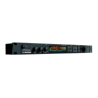
Preamp
Rackmount
BOOST ON
vintage pre-drive
BOOST ON
vintage pre-drive
BOOST ON
vintage pre-drive
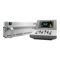
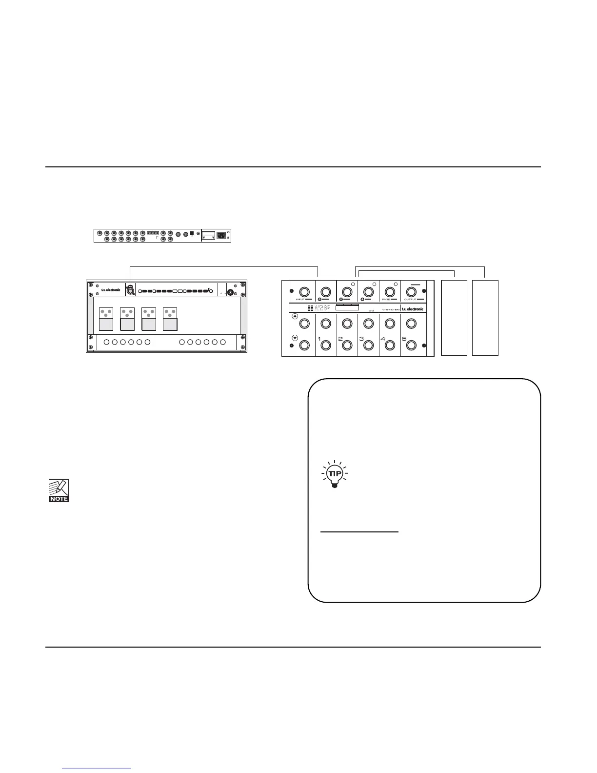
Important!
When the GFX01 is separated from the Control
Board, we strongly recommend mounting a 1
unit standard blank faceplate instead to ensure
maximum stability.
If you do not use a Cat 5 plug with angled
XLR housing, you can turn the wings that
are holding the blank faceplate by 180
degrees to make space for a normal XLR
plug.
This is easily done:
• Unscrew the two screws in each side-panel.
• Turn the wings by 180 degrees.
• Mount the wings again using the screws.
Connections
• Unmount the GFX01 (the 19" unit) from underneath
the Control Board by unscrewing the four 6mm
screws.
• Replace the short CAT 5 cable with a longer cable.
• Mount the 19" GFX01 in your rack.
Please note that some racks require 5mm screws,
while others require 6mm screws. The G-System
is assembled using 6mm screws. Use appropriate
screws for your rack.
For advice on how to connect the drive and
expression pedals, please refer to the descriptions
on the previous pages.
TYPICAL SETUPS
28