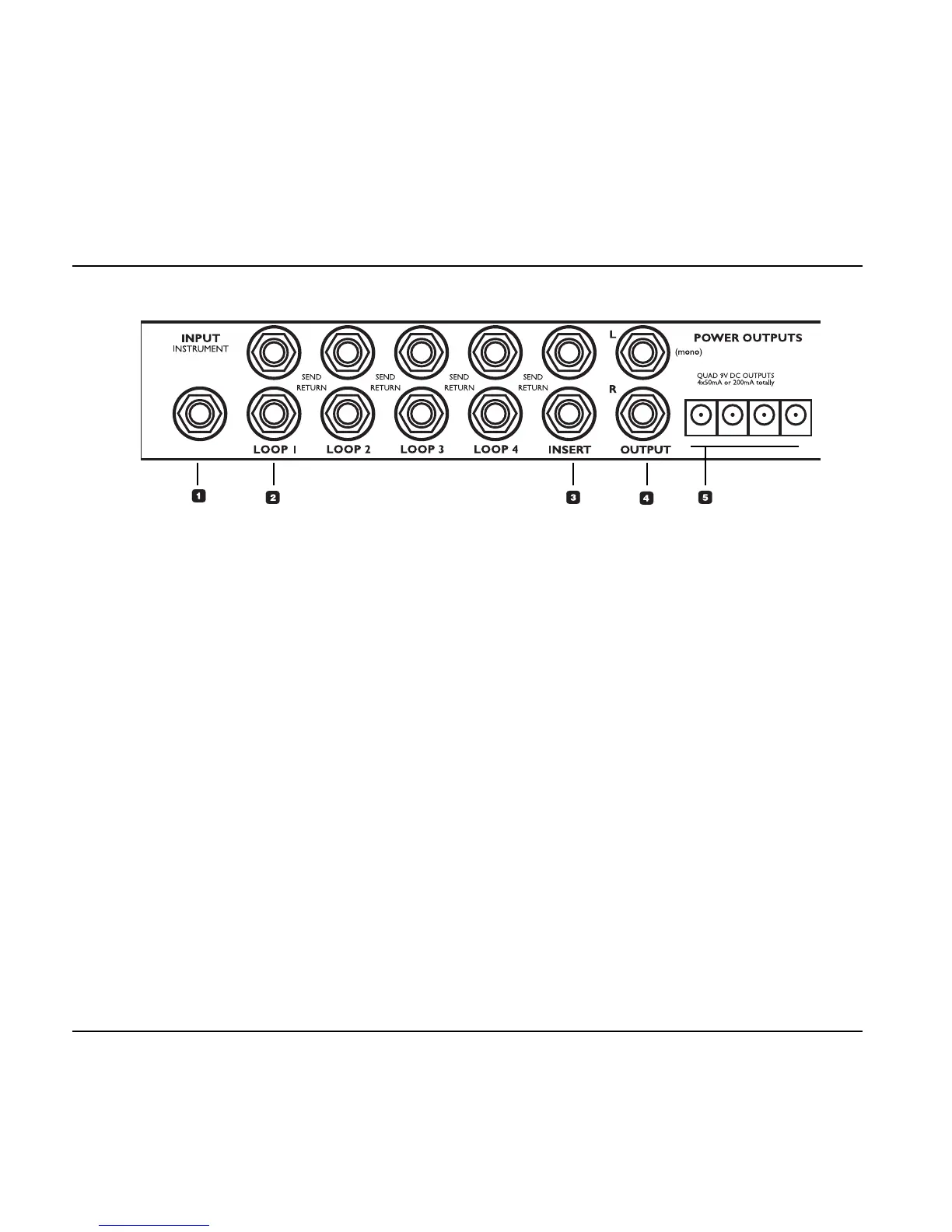
GFX01 – Rear
Input – Instrument
This is the input for your Guitar.
Note: If the G-System is separated and the
GFX01 is mounted in a rack, you may use the
identical Input on the front instead.
Loop 1 to 4
These loops are intended for connecting e.g.
drive/distortion pedals. Use regular unbalanced
jack/jack cables.
Connect a G-System’s “Loop Send” to the input
of the pedal and connect the output of the pedal
to the same loop’s Return connector.
All four loops are constantly sending. A loop only
breaks when the 1/4" Return jack is connected.
This allows you to split your lead signal, feeding
multiple destinations, so you can e.g. use a
Loop Send as a dry signal for a “3-way setup”.
Insert
This loop is intended for a pre-amp. If cables
longer than 3 feet are used, they should be
balanced, even if the connectors on the pre-amp
are unbalanced. When balanced cables are
used, a special pseudo balanced circuit will
reduce the noise which would occur when using
unbalanced cables.
Output
Left/Right output to your amp or amps.
Power Outputs
4 x 9 Volt DC to power connected pedals.
Maximum combined load on these outlets is
200mA. Please check the specifications on
connected pedals: Ring (+), Pin (-).
SW Out (Switch Out)
The two 1/4" stereo jack switch connectors can
be used to switch channels e.g. on a pre-amp or
a combo amp either at preset change or when
sending a CC change.
Switching options are:
– Tip to Ground
– Ring to Ground
– Tip and Ring to Ground
– No Connection
for each of the two connectors.
Depending on the channel switching facilities on
your pre-amp, different cables should be used.
1
2
3
4
5
6
OVERVIEW
20