32
CAUTION:
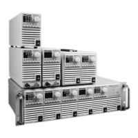
Ensure that the load wiring mounting hardware does not short the output terminals. Heavy connecting
cables must have some form of strain relief to prevent loosening the connections or bending the
bus-bars.
10V to 100V Models
Refer to Fig.3-4 for connection of the load wires to the power supply bus-bars and to Fig.3-5 for
mounting the bus-bars shield to the chassis.
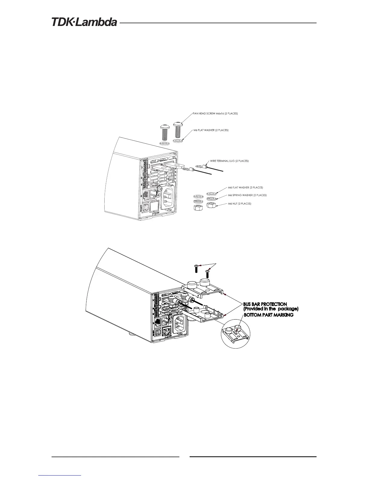
100V Models
WARNING:
There is a potential shock hazard when using a power supply with a rated output voltage greater than
70V. Do not turn ON power supply with rated output voltage above 70VDC without output bus-bars
or output connector protection assembled.
Ensure that the protection of output bus-bars or of output connector is mounted and properly assembled,
and that the bus bar protection is locked by a two SEMS type screws as described in Fig. 3.5
Fig. 3-4: Load wires connection, 10V to 100V models.
Fig. 3-5: Bus-bars shield mounting
BUS BAR PROTECTION
(Provided in the package)
PT SCREW KA40x8 WN1412
(2 PLACES)
BOTTOM PART MARKING