41
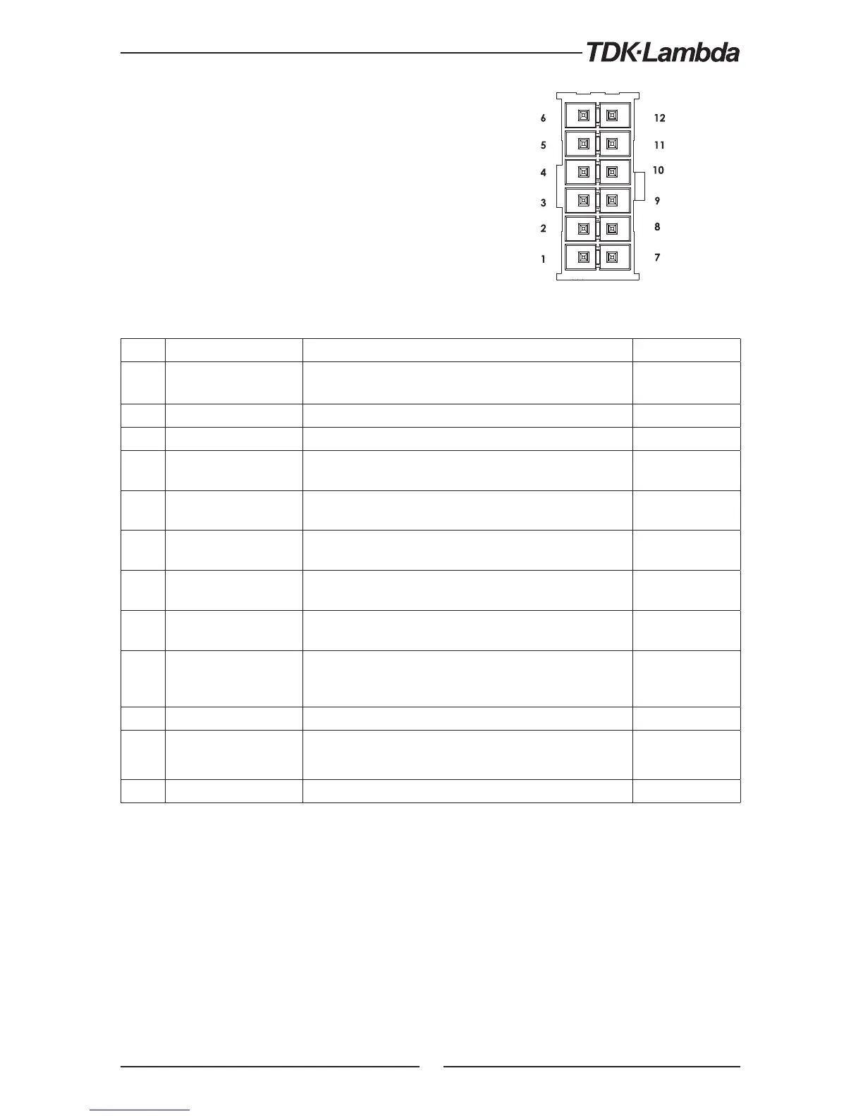
Fig.4-3: J1 connector terminals and functions
Table 4-3: J1 connector terminals and functions
Pin Parameter Specification Section
1 LOC/REM SELECT
Input for selecting between Local or Remote analog
programming of output voltage and output current.
6.2
2 P Output for current balance in parallel operation 5.5
3 I_MON Monitoring power supply output current 6.6
4 LOC/REM MON
Output for indicating if the unit is in Local or Remote analog
programming mode.
5 IPGM
Input for remote analog voltage/resistance programming of
the Output Current.
6.4, 6.5
6 VPGM
Input for remote analog voltage/resistance programming of
the Output Voltage.
6.4, 6.5
7 COM
Control Common. Return for VMON, IMON, CV/CC, LOC/REM.
Connected internally to the negative sense potential (-S).
8 CV/CC
Output for Constant-Voltage / Constant-Current mode
indication.
5.8.1
9 COM
Control Common. Return for VMON, IMON, CV/CC, LOC/REM.
Connected internally to the negative sense potential (-S).
10 V_MON Output for monitoring the power supply Output Voltage. 6.6
11 IPGM_RTN Return for IPGM input.
12 VPGM_RTN Return for VPGM input. Connected internally to the “ -S”.
4.3.1 J1 Connector Terminal and Function
Control and monitoring signals are referenced to the
negative sense potential (-S).
Connector Technical Information:
• Connector type: IPL1-106-01-S-D-RA-K, SAMTEC
• Receptacle type: IPD1-06-D-K, SAMTEC
• Contact pins: CC79R-2024-01-L, SAMTEC
• Hand tool: CAT-HT-179-2024-11, SAMTEC
• Wire: AWG 20-24