33
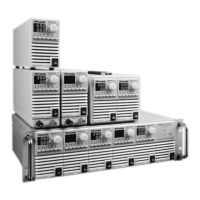
3.9.7 Connecting Single Loads, Local Sensing (default)
Fig.3-6 shows recommended load and sensing connections for a single load. The local sense lines
shown are default connections at the rear panel J2 sense connector. Local sensing is suitable for
applications where load regulation is less critical.
3.9.9 Connecting Multiple Loads, Radial Distribution Method
Fig.3-8 shows multiple loads connected to one supply. Each load should be connected to the
power supply’s output terminals using separate pairs of wires. It is recommended that each pair of
wires will be as short as possible and twisted or shielded to minimize noise pick-up and radiation.
The sense wires should be connected to the power supply output terminals or to the load with
the most critical load regulation requirement.
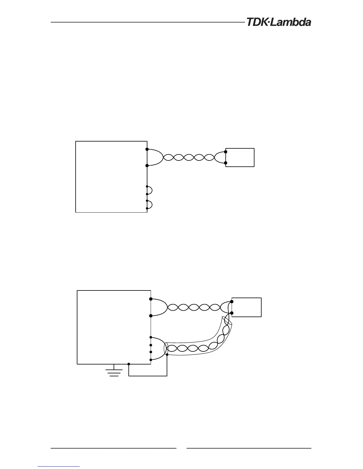
3.9.8 Connecting Single Loads, Remote Sensing
Fig.3-7 shows recommended remote sensing connection for single loads. Remote sensing is
used when, in Constant Voltage mode, the load regulation is important at the load terminals. Use
twisted or shielded wires to minimize noise pick-up. If shielded wires are used, the shield should
be connected to the ground at one point, either at the power supply chassis or the load ground.
The optimal point for the shield ground should be determined by experimentation.
Load
Power
Supply
+V
-V
-Rem. sense
-Local sense
+Rem. sense
+Local sense
+
-
Load lines, twisted pair, shortest length possible.
Fig.3-6: Single load connection, local sensing
Fig.3-7: Remote sensing, single load
Load
Power
Supply
+V
-V
-Rem. sense
-Local sense
+Rem. sense
+Local sense
+
-
Load lines. Twisted pair shortest length possible.
Sense lines.
Twisted pair or shielded.
WARNUNG:
Beim Einsatz eines Netzteils mit einer Nenn-Ausgangsspannung von mehr als 70V besteht
Stromschlaggefahr. Bevor ein Anschluss an der Geräterückseite erstellt oder verändert wird,
schalten Sie die Stromversorgung AUS oder trennen Sie das Netzteil vom Netzstrom. . Stellen
Sie sicher, dass der Schutz der Ausgangssammelschiene oder des Ausgangs aufgesetzt
und angemessen montiert ist, sowie dass der Schutz der Sammelschiene mittels zweier
SEMS-Schrauben verriegelt wurde, wie in Abb. 3.5 beschrieben.