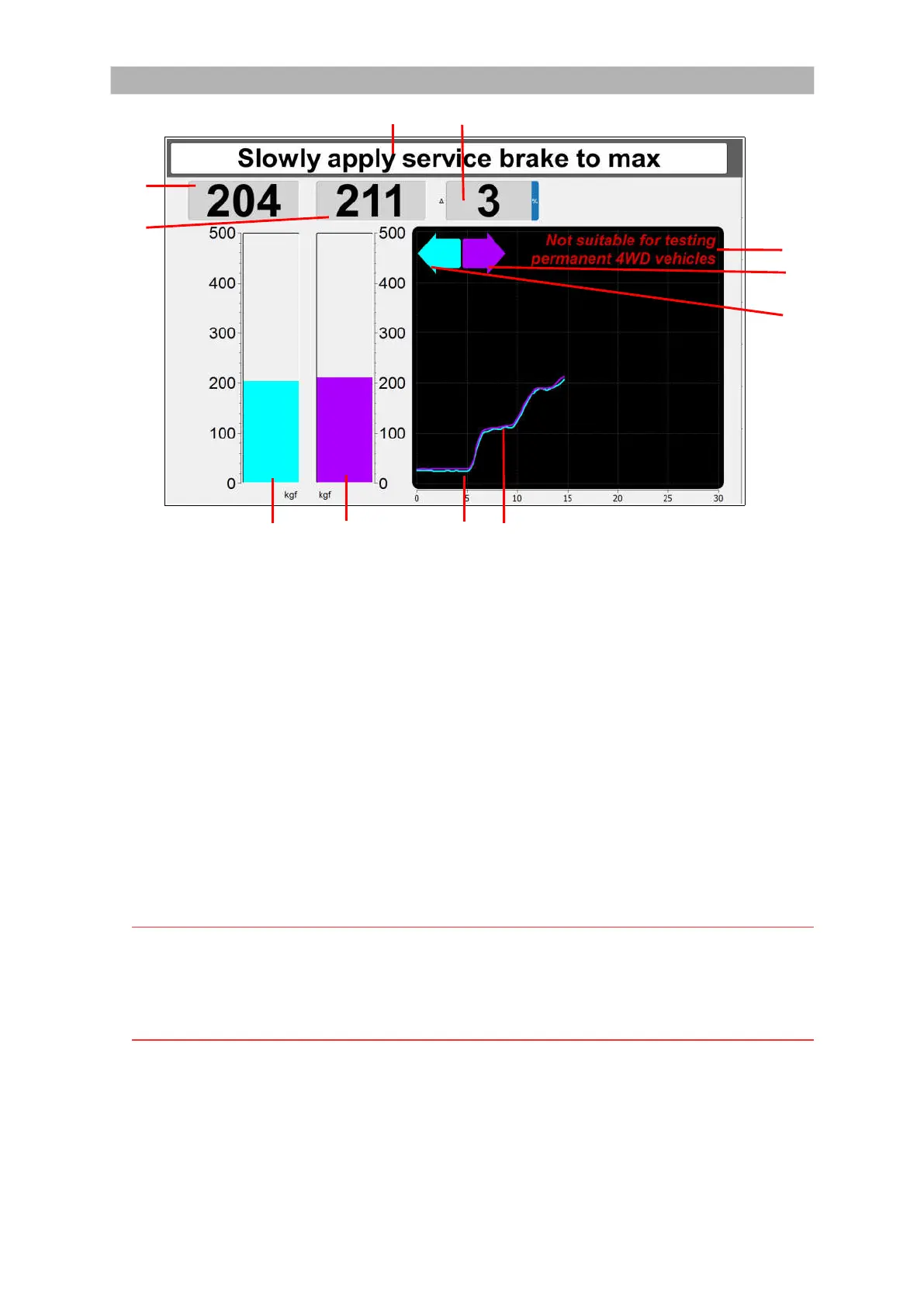
Test screen overview
I J
C
D
K
H
G
A B E F
AREA FUNCTION
A Vertical bar diagram for brake force in KGF for the LEFT wheel of an axle.
B Vertical bar diagram for brake force in KGF for the RIGHT wheel of an axle.
C Brake force in numerical values in KGF for the LEFT wheel of an axle.
D Brake force in numerical values in KGF for the RIGHT wheel of an axle.
E Brake force graph for the LEFT wheel of an axle.
F Brake force graph for the RIGHT wheel of an axle.
G Indicates wheel lock LEFT (slip). When lock occurs, the arrow turns RED.
H Indicates wheel lock RIGHT (slip). When lock occurs, the arrow turns RED.
I Displays the prompts/user instructions.
J Displays the imbalance LEFT/RIGHT in numerical values in % for of an axle.
K Message (fixed): ‘Not suitable for testing permanent 4WD vehicles’.
Note
Brake forces are indicated in kgf.
Weight is indicated in kg.
Imbalance is indicated in %.
Brake efficiencies are indicated in %.
18


 To Next Page