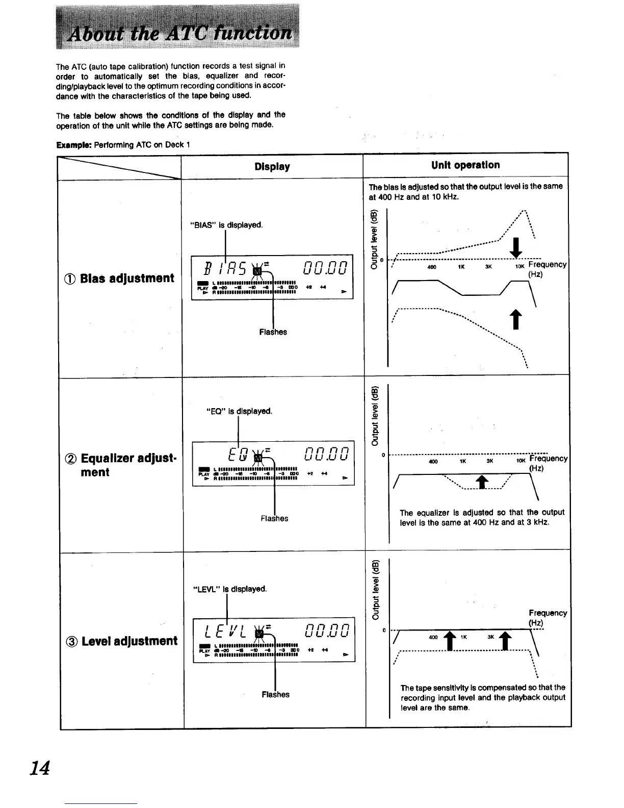
The ATC (autotape calibration)function recordsa test signalin
order to automatically set the bias, equalizer and recor-
ding/playbacklevelto the optimumrecordingconditionsin accor-
dance with the characteristicsof the tape being used.
The table below shows the conditions of the display and the
operation of the unit while the ATC settings are being made.
Display
Example: Performing ATC on Deck 1
Bias adjustment
Equalizer adjust-
ment
Level adjustment
"BIAS" is displayed.
_NI R5 0 __q.L'lu
i _ L lllnlllUllUlnllllll inlnlU
41-10 -18 -10 "6 --_ mO "H! +4
I Rnllnlllllllnlnuul iiiinln _.
Flashes
"EQ" Is displayed.
Eg L?L7.u__,
a / lllllllllllllnnllllll IlOllllll
PLAY Rdliilil_llllll_lllll"i_llll-lll ,llllllnl-3 DD¢ 4-2 +4 lib
Flashes
"LEVL" Is displayed.
I E v// _ I_ I_ 17 I-_
L L L,L,.L,L,
L nnlllllOlllllllllllll IlnllllldB-€O .-116 -10 -4 -3 mO +_ 4"4
b R iiiiiiiinnlulnlllll iiinllll t=-
Flashes
,I• ¸
i i]
Unit operation
The bias Is adjusted so that the output level is the same
at 400 Hz and at 10 kHz.
rn
0
.,.'%
.o
:::::::::::::::::::::::::::::::::::::::::::::::::
' 400 1K 3K 1OK Frequency
(Hz)
/ ..........................:..... T
"'4,
rrl
_¢
"4,
"'4**
\
................................................ _°o..
400 1K 3K 1OK Frequency
(Hz)
/ .....t i \
m
_e
"5
0
The equalizer Is adjusted so that the output
level is the same at 400 Hz and at 3 kHz.
Frequency
(Hz)
The tape sensitivity Is compensated so that the
recording input level and the playback output
level are the same.
14
 Loading...