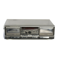
RS・TR575
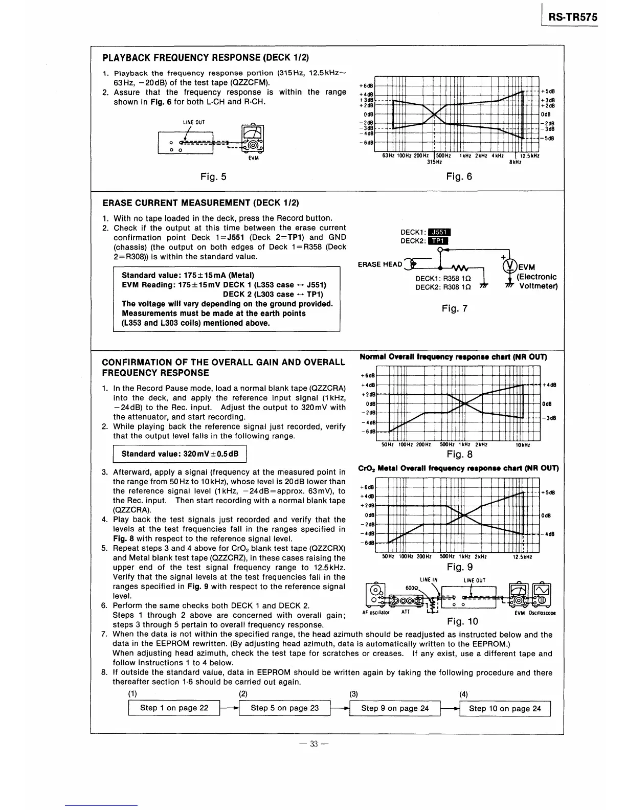
PIAYBACK FREQUENCY RESPONSE(DECK1,2》
1.PlaybaGk the frequenGy response portlon(315Hz,12.5kHz〜
63Hz,一20dB)of the test tape(QZZCFM). +6dB
2.Assure that the is within the
+4de
+5d8
+3dB
+2d8
0dB
鵬
咽
}
frequency response range
shown in Fig.6for both L・CH and R・CH.
+3dB
+2dB
OdB
−2dB
−3dB
『
閣
十
L
l l
−
「
H I−
l I皿
』
『
1
1 一
ノ
!
一
[1
川1
UNE OUτ ^
1
1
へ1
\
1[
Iill
団
冒
■
十
1
l I 一一
、
一
→冊
ρ
ロ ー
2dB
−3d8
∠
一466
;
1
1︐1
1
O G『・一一。一一_
o ◎
D_一1
就
一6dB
1−1
:
1
1
覗 一5de
q
一 噸
.5kHZ
Fig.
』。.
5
v v
∈VM
63Hz↑00Hz200HZ
315Hz
500Hz l kHz2kHz4kHz
8kHz
Fig.6
(chassis)(the output on both edges of Deck1=R358(Deck
2ニR308))is withln the standard value.
ERASECURRENTMEASUREMENT(DECK1,2》
1.With no tape Ioaded in the deck,press the Record button.
2.Check if the output at this time between the erase current
DECKll■固■
c・nfirmati・np・intDeck1ニ」551(Deck2ニTP1)andGND DECK2:囮■
O鴫
EVM
(Electronic
Voltmeteり
Standard value=175±15mA《Me量al》
EVM Readlng=175±15mV DECK1(L353case⇔」551》
DECK2(L303case←・TP1》
The vo脆age wlvary depending on量he ground provided.
Measuremen量s mus量be made ahe earth points
(L353and L303coils》mentioned above.
十
ERASE円EAD) {}W㌧
DECK1:R3581Ω
DECK2:R3081Ω 男7
Fig.7
owlng range.
atthemeasuredp。intin C『02
+6d8
63mV》,to
+4dB
with a normal blank tape
+2d3
0d8
−2dB
ranges specified in
−468
signalleveL −668
blank test tape(QZZCRX)
in these cases raising the
range to12.5kHz.
frequencies fa旧n the
omalO》●『88Dqo●cy『●8po8●ch●d醐OUη
1
CONFIRMATlON OF THE OVERALl GAIN AND OVERAll
FREQUENCY RESPONSE +66B
−
+4d3
!
+4d6
+26B
li
、
、
よ
[
1、lnthe Record Pausemode,Ioad anormaI blanktape(QZZCRA)
into the deck,and apPly the reference input signal(1kHz,
一24dB)to the Rec。input. Adjust the output to320mV with
the attenuator,and start recordi ng,
2.While playing back the reference signal just recorded,verify
Od8
−26B
』1
イ
i
「1
一
i︑
一噂
一
冒
一4d8
−6d8
i
that the output level falls in
the foll
打
【
50Hz100Hz200Hz 500HzlkH12kHz 10kHz
Fig.8
顛●ね10》●ro響r●qu●cy r●8poo9●c馳8rt{腕OUT》
S量andard value=320mV±0.5dB
Od8
−308
+5d8
0d3
3.Afterward,apply a signal(frequency
the rangefrom50Hzto10kHz),whoselevel is20dB lowerthan
the reference signal Ievel(1kHz,一24dBニapProx.
the Rec、input. Then start recording
(QZZCRA》.
4. Play back the test signals just recorded and verify that the
levels at the test frequencies fal l i n the
Fig.8wlth respect to the reference
5、Repeat steps3and4above for CrO2
and Metal blanktesttape(QZZCRZ),
upPer end of the test signal frequency
Verify that the slgnal Ievels at the test
ranges specified in Fig.9with respect to the reference signal
IeveL
6.Perform the same checks both DECK l and DECK2.
Steps l through2above are concemed with overall gainl
steps3through5pertain to overafrequency response.
7.When the data is not within the specified range,the head azimuth
data in the EEPROM rewritten,(Byadlusting head azlmuth,datais
When adjusting head azimuth,check the test tape for scratches
foow instructions l to4below.
8.If outside the standard value,data in EEPROM should be written
thereafter section1・6should be carried out again.
(1) (2) (3)
一!,.
冒
1!
目
!
F
1
口
、
淋
1
1[
壮
1
T1
1レ1
l l
\
鞠
陶⊥.
■
1
ξ
一46B
1
:
A
600Ω
σσQσ
50Hz 100Hz 200HZ 500Hz l kHz 2区Hz 12.5kHl
Fig.9
u飼E I冠
1陶E OUT ^
◎O
_毫 α』一一_一一
〇 ◎
1、_
飛
り◎
竪
l Step1・npage22
1−1
Step5・npage23HStep9・npage24
AF osCIlla!Of ATY
should be
automatically
or creases. lf
again by taking
1
し
readjusted
written
any
the
1︐﹂
}
05Cll㎏5cope
Fig.10
as instructed below the
to the EEPROM.)
exist,use a different tape and
foIIowing procedure and there
(4)
Step100n page24
V V V
∈V闇
and
一33一