(By
HEAD REPIACEMENT
When replacing the head,adjust the head azimuth as
adjusting head azimuth,data isautomaticaIlywritten tothe
(1) (2)
instructed
below,
EEPROM.)
and
rewrite
the data to the
EEPROM.
are
1
lStep1・npage22 }Step8・npage23
(4》 (3)
IStep1・・npage24( Step9・npage24
1司
(The
by
adjustment is necessary becausethe playback gain,the overagain,
the head replacement.)
and
the overafrequency
response
ー ハ∠3五﹃
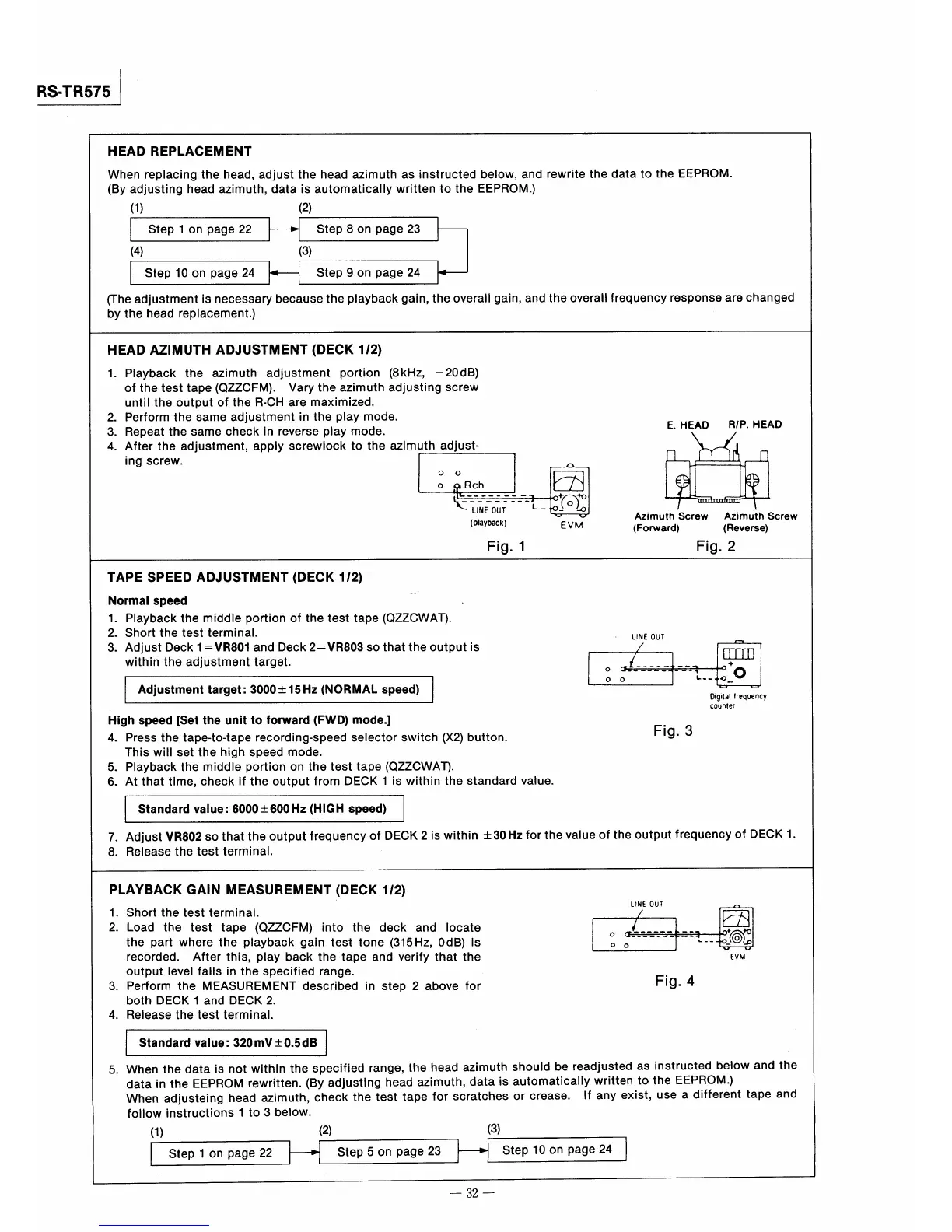
HEAD AZIMUTH ADJUSTMENT(DECK12》
Playback the azimuth adlustment portion (8kHz,
ofthetesttape(QZZCFM). Varytheazimuth adjusting screw
untiltheoutputofthe R−CH are maximized.
Perform the same adjustment in the play mode.
Repeat the same check in reverse play mode.
After the adjustment,apply screwbck to the azimuth adjust・
一20dB)
讐轟、ヂ・』λ.8凱
(
Azimuth
(Forward》
E.HEAD
RP.
ing screw.
O O
O
団
〔Playbackl
Fig。
1
Screw
Fig.
一
(Reverse)
V V
EVM
2
﹂ーハ∠
TAPE SPEED ADJUSTMENT《DECK12)
Normal speed
Playback the middIe portion of the test tape(QZZCWAT).
Short the test termlnal.
output
the value
し崩E OUT
一
3.
Adjust Deck1=VR801and Deck2ニVR803so that the
is
within the adjustment target.
∠
皿つ
→P
0 (f一___幽二
一一
一幅■
0
AdjustmenUarget=3000±15Hz《NORMAしspeed)
O O
L購一ゆつ
一
of the output
一
Dlgl電al
lrequency
4.
5.
6.
High speed【SeUhe unit to fo㎜ard(FWD》mode.I
Press the tape−to−tape recording・speed selector switch(X2)
This will set the high speed mode.
Playback the middIe portion on the test tape(QZZCWAT).
At that time,check if the output from DECK l ls within the
2
button.
standard
value.
Fig.3
coun重er
S量andard value=6000±600Hz(HIGH speed》
7只︾
Adjust VR802so that the output frequency of DECK
Release the test terminaL
is within±30Hz
for
frequency
of
PLAYBACK GAlN MEASUREMENT(DECK12》
should
or crease.
aUtOmatiCay
lf
し陶E OUT
=ニコ
A
1.
Short the test terminaL
団.≦就
2.
Load the test tape (QZZCFM)into the deck
the part where the playback gain test tone(315Hz,OdB)
and locate
is
/
0 α二「.凱=■
O o
』一
v
)
3 4
recorded. After this,play back the tape and verify that
output level fas in the specified range.
Perform the MEASUREMENT described in step2
both DECK l and DECK2.
Release the test terminal、
above
the
for
be readjusted as instructed
written to the
any eXiSt,USe a
Fig.4
〔V}
S量andard value=320mV±0.5dB
5.
When the data is not within the specified range,the
data in the EEPROM rewritten.(By adjusting head
When adjusteing head azimuth,check the test tape
follow instructions l to3below.
(1》 (2》
head
azimuth,
azimuth
data is
for scratches
(3》
EEPROM.)
different
231
1
Step10
on page
24
Step1・npage2211Step5・npage
「
一32一