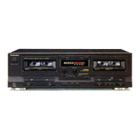
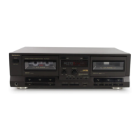
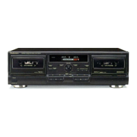
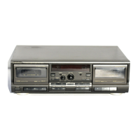
RS・TR575
■DlSASSEMBLY lNSTRUCTlONS
AT『EN層『10N SERV醒CER,,
Some chassis components may have sharp edges.
Be careful when disassembling and servicing.
Ref.No.
1
Procedure
1
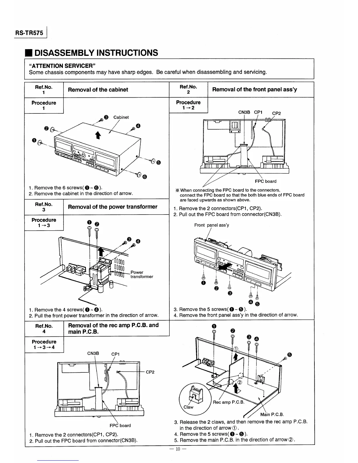
Removal of the cabinet
③
.!ゆ
②猷.
舎
o猷・§。鎌
§馨§
輸
Cabinet
④
.ノゆ
\・@⑤
\噸⑥
1.Remove the6screws(①〜⑥).
2.Remove the cabinet in the direction of arrow.
Ref.No.
3
Removal of the power transformer
P『ocedu『e
1→3
u
マ?
ヤ
、 ノ㊦③
コ旗ノ
《
島而000
11000
蓮
①②
④
Power
transformer
1.Removethe4screws(①一④)。
2.PuII the front power transformer in the direction of arrow.
Ref.No.
4
Removal of the rec amp P。C.B.and
main P.C.B.
Ref.No.
2
Procedure
1→2
Removal of the front panel ass,y
CN3B CP1
ノ
)r∠
/ n【/
、
)
田o
●
︐励
1
論
、
盟/
→
■〕 /
A、一,,,1,i
lHUm期 i 〔,
1 / /
\
1
//〕〕F売一d
CP2
※When connecting the FPC board to the connectors,
connect the FPC board so that the both blue ends of FPC board
are faced upwards as shown above。
1,Remove the2connectors(CP1,CP2).
2.Pull outthe FPC board from connector(CN3B),
Front panel assy
講鎌
ムi轄§
・齢 疇
③ 輔
④⑤
3,Remove the5screws(①〜⑤),
4.Remove the front panel assy in the direction of arrow.
Procedure
1→3→4
①
CN3B
CP1
、 /
!廿
一 一
一
1
冨
1 〔
−
〜
r『、 )
乳
〔鼎、,,1,1
1川口ll旧
\ 1
〕 \
FPC board
1.Remove the2connectors(CP1,CP2)。
2,Puoutthe FPC board from connector(CN3B)、
CP2
Claw
②
1
喰
馨
Rec amp P,C.B、
③④
、
⑤
.ノ声
Main P,C.B,
3,Release the2claws,and then remove the rec amp P、C.B.
inthedirectionofarrow①.
4.Remove the5screws(①一⑤).
5.Remove the main P.C,B,in the direction of arrow②.
一10一