RS・TR575
Rear paneI
ρo
ll
\
㊦
⑨
For[P,PCl areas.
!へ、
︾層⑥
阜繭⑥
⑧⑦ ⇒
脚
/
噛
無
9
◎
◎
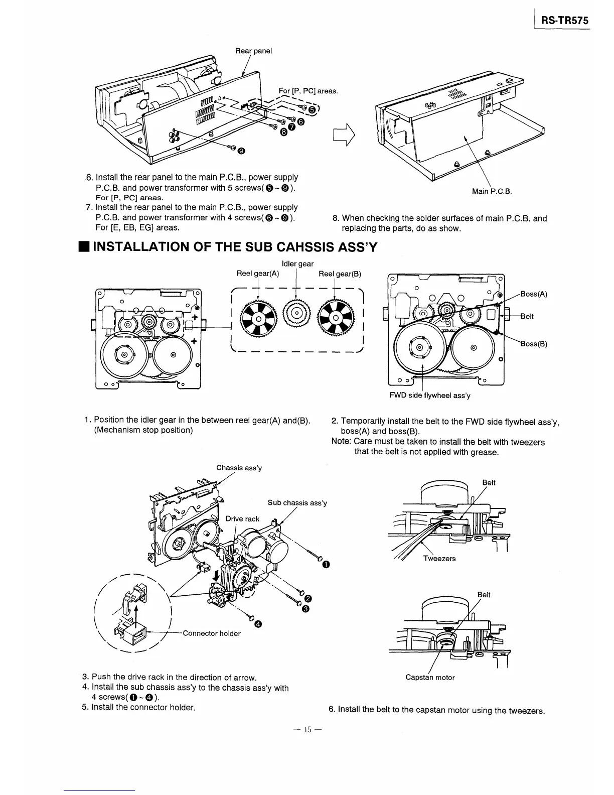
,6,lnstall the r6ar panel to the main P,C.B.,power suppIy
P,C,B.and power transformer with5screws(⑤〜⑨).
For[P,PC]areas。
7jnstall the rear panel to the main P.C,B、,power supply
P.CB。and power transformer with4screws(⑥〜⑨).
For[E,EB,EGl areas,
Main P,C.B.
8.When checking the solder surfaces of main P.C.B.and
replacing the parts,do as show.
■INSTALLATlON OF THE SUB CAHSSIS ASSY
o
o
O
○◎
十
I l◎ ◎ ◎1
◎
◎
十
o
0◎
o
Idler gear
搾1騨)一蹄讐Bl
\喚_________ノ
び )
O
O
⑤ o
⑨
じ「・1
・ 口・
/コ\
◎・
o。う「
◎ ot
。 、
Boss(A)
Be[t
Boss(B)
FVVD side flywheei assy
1、Position the idler gear in the between reel gear(A)and(B).
(Mechanism stop Position)
2.Temporarily instaII the beltto the FWD side flywheel assy,
boss(A)and boss(B),
Note:Care mustbetakento instathe beltwithtweezers
that the belt is not applied with grease.
Chassis assy
Belt
σ
0
、o
Subchassisassy
Drive rack
ノ ペ
/ \
@
⑦
3
(峯一一緬
、ノ
①
ノ
㌔
④
曾
り\
①
ヤ②
③
Tweezers
Belt
〜
3.Push the drive rack in the direction of arrow.
4.Instathe sub chassis assy to the chassis assy with
4screWS(①一④).
5.lnstallthe connector holder.
Capstan motor
6」nstall the belt to the capstan motor using the tweezers.
一15一