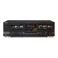
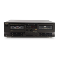
RS・TR575 RS・TR575
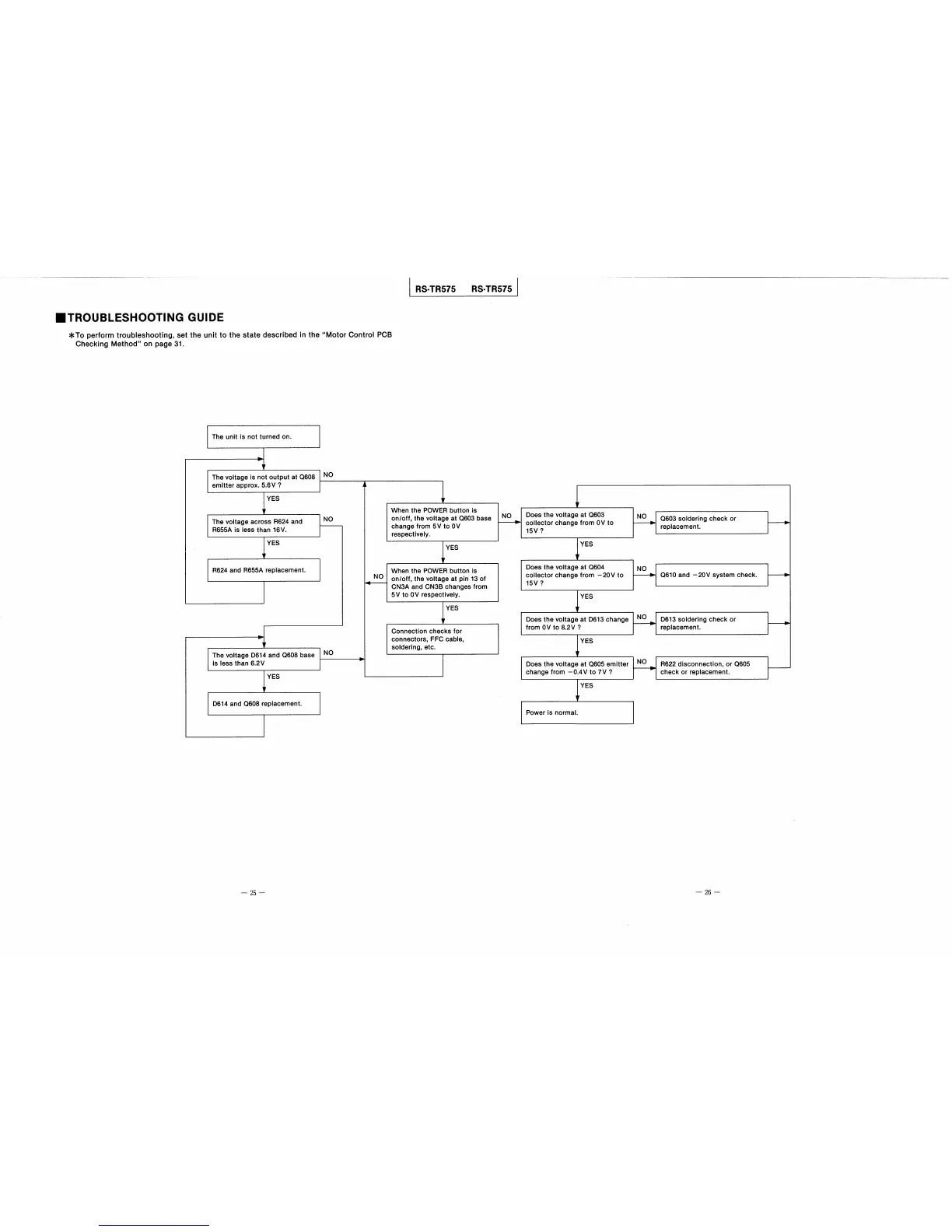
■TROUBLESHOOTING GU置DE
*To perform troubleshooting,set the unit to the state described in theMotor Control PCB
Checking Methodon page31、
The unit is not turned on.
The voltage is not output at Q608
emitter apProx.5.6V?
NO
YES
The voltage across R624and
R655A is less than16V.
NO
YES
R624and R655A replacement.
The voltage D614and Q608base
is Iess than6.2V
NO
YES
When the POWER button is
onloff,the voltage at Q603base
change from5V to OV
respectively、
NO
YES
Does the voltage at Q603
coIlector change from OV to
15V?
NO
NO
YES
Q603soldering check or
replacement.
When the POWER button is
onoff,the voltage at pin130f
CN3A and CN3B changes from
5VtoOV respectively.
YES
Does the voltage at Q604
collector change from−20V to
15V?
NO
YES
Does the voltage at D613change
from OV to8.2V?
Q610and−20V system check.
Connection checks for
connectors,FFC cable,
solderlng,etc。
NO
D613soldering check or
replacement。
YES
Does the voltage at Q605emitter
change from−0,4V to7V?
D614and Q608replacement、
NO
R622disconnection,or Q605
check or replaCement.
YES
Power is normal.
一25一
一26一